Grid Improvement Strategies and Techniques
1.3 Enlargement of the Hexahedra Layer via Grid Manipulation
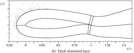
The task of the first grid manipulation tool is to enlarge the structured layer in order to move the hybrid border out of flow regions with gradients. This is achieved by moving the grid points that are located along the hybrid border. These points are moved along wall normal lines of the structured layer. These lines have to be extrapolated into the unstructured grid region in a way that prevents twisting and overlapping of these lines. To assure this, a line extrapolation method similar to those in structured grid generators is used.
 |
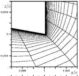 |
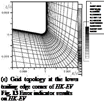
(c) Lower trailing edge corner of HK-EV (d) Lower trailing edge corner of HK-Fein
(f) Grid topology at the lower trailing edge corner of HK-Fein
In the following the proceedings of the tool are described in more detail. After loading the grid the tool determines the surface triangles and quadrilaterals as well as the grid points that shape the hybrid border. Thus a new surface geometry constituted by the surface triangles and quadrilaterals is obtained. Based on this surface a grid of user-defined thickness is generated via wall-normal extrusion. This extrusion is performed according to the methods described in [11] and [12]. To ensure a consistent extrusion of the wall lines, the marching vectors of the extrusion are
 |
z/c
 |
1 і 1 і 1 і 1 і 1 і 1 і 1 і 1 і 1 і 1 і 1 і 1 і 1 і 1 г -0.25 0 0.25 0.5 0.75 1 1.25 1.5
smoothed [13] in a way that ensures that the visibility cone condition [12] is not violated.
The newly generated points form a new surface geometry on which the extrusion process is repeated. These steps are repeated until a certain number of extrusion layers have been obtained. The resulting grid points are used to define the extrapolated wall lines. Along these wall lines, the new coordinates of the corresponding grid points which shape the hybrid border are moved. To avoid a steep transition from the undeformed to the deformed region, neighbouring points up to a certain degree are included in the movement. This transition is based upon a hyperbolic tangent. After the coordinates of each affected hybrid border grid point have been determined, the points lying below are redistributed. Thereby, discontinuities in the grid point distribution along wall lines are prevented. This redistribution is performed via an area hyperbolic sinus function according to [14]. The coordinates of the affected grid points are stored in a binary file. The manipulation of the grid is performed by a modified version of the DLR-TAU-Code’s deformation tool [15] which uses this binary file.
![]()
|
To demonstrate the method, the 3D-grid of the DLR-F6-wingtip with 1.2 million grid points, in Figure 15, is used. Grid lines on the geometry surface are shown by fading out portions of the volume grid. Furthermore, the box which marks the region to be deformed is plotted. This box is defined by the four coordinates P1 (x, y, z) to P4 (x, y, z). Multiple overlapping boxes can be defined.
 |
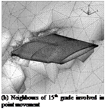 |
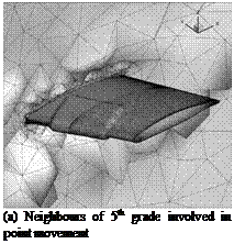
The result of the deformation is illustrated in Figure 16(a) by showing the prism and hexahedral layers. The enlarging effect can clearly be seen. In this case, neigh – bourings points of fifth grade have been involved to the deformation. This yields a steep and unsmooth transition from the undeformed to the deformed grid region. To get a smoother transition the whole manipulation process was rerun with neigh-
|
|
||
bours of 15th being involved. As shown in Figure 16(b), this yields a much smoother transition.
For better illustration, the prismatic and hexahedral layers are shown at two slice planes through the volume grid in Figures 17(a) and 17(b). These Figures show that the transition from the undeformed region to the deformed region is smooth.
In summary, the tool is capable of enlarging the structured layer of a hybrid grid by moving grid points. The degree of enlargment is closely related to the quality of the surface elements forming the hybrid border. If a badly shaped surface element is present at the hybrid border i. e. an element with very high skewness, the ability of the tool to enlarge the structured layer at that location may be limited. However in regions with good element quality, very large deformations are possible.


