The Hoppers
Tn 1 QfY7 dhrviit fmir t/Aare aftpr fliA X/n rrbf РгліКрґє’ firet eiiAPPecfnl плп/агаН fli rrVitc
J. U X S J / 9 UOVVH JLVtU J VU1 О UltVJ. 111V П 1 iglll JJ JL J lllC/1 О 111. Ol OUWVOOl U1 JJV vr V1VU lll^llto
in fixed-wing airplanes at Kitty Hawk in the United States, Paul Cornu of France constructed a helicopter that is reported to have carried a human off the ground for the first time. Boulet (1984) gives a good account of the work. Although Cornu had conducted experiments with small rotor models, he lacked the necessary theoretical understanding of rotor aerodynamics and performance to enable these results to be properly scaled to a full-size helicopter. Such theoretical analyses were not to be widely understood and used until the 1920s. Cornu’s machine (Fig. 1.7) used a skeletal airframe of very simple construction and relatively light weight, being constructed of a 20 ft (6.1 m) length of steel beam bent into a wide U-shape, with six “star” frames all tied together with cables. A rotor was mounted at each end of the main structural beam. The rotors rotated in opposite directions, a necessary requirement to cancel torque reaction. The inner hub part of each rotor looked like large bicycle wheels. At the periphery of each rotor, there were two light, wide-chord and fabric-covered blades. Power was supplied to the rotors by a 24 hp (17.9 kW) Antoinette gasoline motor through a driving belt and pulley transmission, a mechanism that it seems caused Cornu many
пглЫргпс onH тплЬ fmctrofmn толіітл cof лп – Рглпг Кютгліа urVtApIo Л пмтіНігл
иичд 111UVU АХ UJ LA UtiV/ll. 1 UV VV UU1V lliaVllillt’ oai V/ll 1VU1 VYllC’t/lO. n pilllliLl w
means of control was achieved by placing a “plane” or a wing in the slipstream below each of the rotors; the inclination and force on the these wings was controlled by the pilot with two hand operated levers. On November 13, 1907, at Normandy in France, Cornu’s “flying bicycle” was reported to have made several tethered flights of a few minutes at low altitude. In Cornu’s own words, “… the aircraft left the ground with four wheels all together….”
|
Figure 1.7 The Cornu helicopter, circa 1907. (Courtesy NASM, Smithsonian Institution, SI Neg. No. 74-8533). ■ |
|
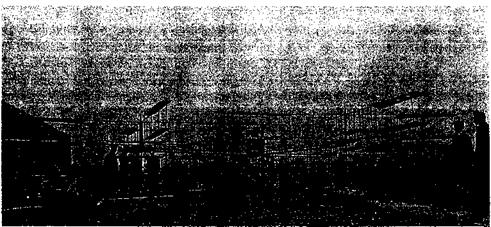
Figure 1.8 The Breguet Gyroplane No. 1, looking somewhat like an assemblage of ladders, made some uncontrolled hops off the ground in 1907. |
However, no supporting photographs or eyewitness accounts of his flights have ever been produced. See Boulet (1984) and Leishman (2001a) for further details.
In 1904, the French scientist Charles Richet built a small unpiloted helicopter. Even then, Richet was well-known for work in aerodynamics and had given many lectures on the subject at the French Academie des Sciences. One of Richet’s students, Louis Breguet, was soon to become a famous aviation pioneer. During the latter part of 1906, the Breguet Brothers had begun to conduct helicopter experiments under the guidance of Richet. In 1907 the Breguet Brothers made experiments with a rotary-winged test rig with a force-balance [see Breguet (1936)] and shortly thereafter they built their first helicopter. Their ungainly quadrotor Gyroplane No. 1 consisted of four long girders made of steel tubes and arranged in the form of a horizontal cross (Fig. 1.8). A rotor consisting of four biplane blades was placed at each of the four comers of the cross, giving a total of 32 separate lifting surfaces. The pilot sat in the center of the cross next to the 40 hp (29.8 kW) engine. The machine is reported to have carried a pilot off of the ground into free flight, albeit briefly. These claims may have been exaggerated because photographs show the assistance of several men stabilizing and lifting the machine. Clearly, the machine could never have flown completely freely because, like the Comu machine, it lacked flight stability and a proper means of control. However, the Breguet machine was probably closer to achieving vertical flight than the one made by Paul Cornu – see Boulet (1984) and Leishman (2001b).
Aldridge (1954) describes a helicopter that was built by the designer Edwin Mumford at the William Denny & Brothers’ shipyard in Scotland during 1905. This helicopter consisted of six two-bladed rotors, which were mounted on each side of a skeletal frame. The rotors looked much like ship propellers and could not have been efficient for use in air. Control was provided for by tilting the rotor shafts, with a rudder at the tail for directional control. It is claimed that tethered and free flights of the helicopter were made during 1909, where the craft apparently reached altitudes of 10 ft (3.05 m) and forward speeds of 20 mph (32.2 km/h). Tests apparently continued through to 1914, when the machine was destroyed in a storm. Further work on the project was abandoned because of the start of WW1. See Rees (1990) for further details.
In the early 1900s, Igor Sikorsky and Boris Yuriev independently began to design and build vertical-lift machines in Czarist Russia. By 1909, inspired by the work of Comu,
Breguet, and other French aviators, Sikorsky had built an unpiloted coaxial helicopter prototype. This machine did not fly because of vibration problems and the lack of a powerful enough engine. Sikorsky (1938) stated that he had to await “better engines, lighter materials, and experienced mechanics.” His first design was unable to lift its own weight and the second in 1910, even with a more powerful engine, only made short (nonpiloted) hops. Discouraged, Sikorsky abandoned the helicopter idea and devoted his skills to fixed-wing (conventional airplane) designs at which he was very successful. Although Sikorsky never gave up his vision of the helicopter, it was not until the 1930s after he had emigrated to the United States that he pursued his ideas again (see later). Good accounts of the life and work of Igor Sikorsky are documented by Bartlett (1947), Delear (1969), Sikorsky (1964, 1971), Sikorsky & Andrews (1984), Finne (1987), and Cochrane et al. (1989).
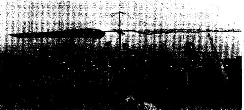
The famous Russian aeronautical engineer Konstantine Antonov had also built a prototype coaxial rotor helicopter about 1910. A propeller was used for forward propulsion. The rotors were about 20 ft (6.1 m) in diameter and consisted of many triangular shaped blades. A collective pitch mechanism was used to change the pitch of the blades, which could be set into flat pitch forming a flat disk. The machine did not fly. Unbeknown to Sikorsky, Boris Yuriev had also tried to build a helicopter in Russia around 1912, but with a somewhat modem looking single rotor and tail rotor configuration (Fig. 1.9). This was a revolutionary concept for the time compared to all of the multirotor machines being built, and the concept was patented in 1911. Like Sikorsky’s machine, however, Yuriev’s helicopter lacked a powerful enough engine. Good accounts of Yuriev’s machine are given by Gablehouse
(1967) , Everett-Heath (1988), and Liberatore (1998). Yuriev was to guide Soviet helicopter development and trained a number of leading Soviet designers, including Mikhail Mil. He was also to author a book, The Aerodynamic Design of Helicopters, which was published in Russian in the early 1950s.
Besides being one of the first to use a tail rotor design, Yuriev was another one of several firsts to propose the concept of cyclic pitch for rotor control using a form of swashplate. However, he did not actually use the cyclic mechanism on his 1912 machine. Another early cyclic pitch concept was patented by Gaetano A. Crocco of Italy in 1906. Crocco, who was an engineer and prolific inventor, recognized that if a helicopter was to work properly, a means of changing the pitch on the blades would be needed to account for the
|
Figure 1.9 In 1912 Boris Yuriev of Russia built helicopter using a single rotor and tail rotor for anti-torque, but it did not fly for want of a suitable engine. |
dissymmetry in the airflow between the side of the rotor advancing into the relative wind and the side retreating away from the wind when in forward flight. The concept of cyclic pitch was one key to attaining full control of the helicopter, although the successful mechanical implementation of this concept was not to occur for many more years until it was properly married with the flapping hinge.
Professor Zhukovskii (Joukowski) and his students constructed a primitive coaxial helicopter at Moscow University in 1910 – see Gablehouse (1967) and Everett-Heath (1988). Joukowski is well known for his theoretical contributions to aerodynamics and he published several papers on the subject of rotating wings and helicopters – see also Margoulis (1922) and Tokaty (1971). While Rankine and Froude had already established the general theory of propellers and rotors using momentum theory prior to 1890 (see Chapter 2), there were a number of other notable developments in the basic aerodynamic theory. The Frenchman Drzewiecky had developed a hybrid momentum-blade element concept as early as 1900 and in 1909 he published a book on rotors titled “Des Helices Aeriennes Theorie Generale des Propulseurs.” In 1904, Joukowski published a paper titled “On the Useful Load Lifted by a Helicopter.” In 1906, Joukowski’s better known work “About Connected Vortices” was published. A year later a paper titled “A Multi-Bladed Propeller-Screw” appeared. In 1909 Joukowski investigated the theory of the effects of forward flight speed on a rotor. This paper was titled “Experiments on the Theoretical Determination of the Effect of the Airflow on the Surface of a Propeller.” Here Joukowski proved that because of the nonaxisymmetric distribution of velocity and airloads, asymmetric forces and moments act on a propeller in edgewise flight. Of course, this implied that to control a helicopter such that it could fly forward would be a difficult task indeed. Although this problem was later solved with the invention of cyclic blade pitch control and the incorporation of blade flapping hinges, Joukowski offered no method of solution in his paper.
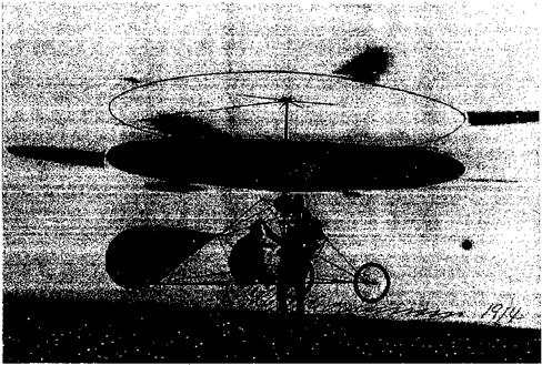
About 1912, the Danish aviation pioneer Jacob C. Ellehammer designed a coaxial rotor helicopter. Boulet (1984) gives a good description of the machine, which is shown in Fig. 1.10. The rotor blades themselves were very short; six of these were attached to the periphery of each of two large circular rings of about 20 ft (6.1 m) in diameter, with the blades extending out about another 5 ft (1.52 m). The lower disk was covered with fabric and was actually intended to serve as a parachute in the event the blades or the engine failed. A cyclic pitch mechanism was used to change the pitch of the rotating blades and provide control, this being another one of many early applications of the cyclic pitch concept. The pilot was supported in a seat that could be moved forward and sideways below the rotor, allowing for additional kinesthetic control. This helicopter made many short hops into the air but it never made a properly controlled free flight. It was finally destroyed in a crash, although it carries the distinction of being one of the first early helicopters to be photographed in free-flight.
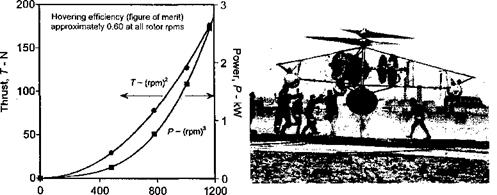
An Austrian, Stephan Petroczy, with the assistance of the well-known aerodynamicist Theodore von Karman, built and flew a coaxial rotor helicopter (Fig. 1.11) during the period 1917-1920. Interesting design features of this machine included a pilot/observer position above the rotors, inflated bags for landing gear and a quick-opening parachute. The machine was powered by three rotary engines, a good example of redundancy in the event of an engine failure. Although the machine never flew freely, it accomplished numerous tethered vertical flights restrained by cables. It was actually used for military observation, and was a more economical and easily recovered alternative to observation balloons. The work is summarized in a report by von Karman (1921) and published by NACA. It is significant that von Karman also gives results of laboratory tests on the rotors, which were really oversize propellers. The results (see Fig. 1.11) agree with elementary rotor theory
|
Figure 1.10 Danish aviation pioneer Jacob Ellehammer flew a coaxial rotor helicopter design in 1912. |
in that the thrust and power should increase with the square and cube of rotor rpm, respectively (see page 54), and had a decent hovering efficiency of 60% (i. e., a figure of merit of 0.6 – see discussion in Section 28).
By the end of the nineteenth century there is more evidence that scientific means were being used to understand the lifting capability of rotors and the power required for vertical flight, especially in Britain and France. In the 1860s, F. H. Wenham had made experiments with a two-bladed airscrew in an attempt to measure the forces produced. He was able to conclude that the laws governing the behavior of a propeller in air were the same as for water.
|
Rotor rpm Figure 1.11 The rotor performance of the Petroczy helicopter was measured by Theodore von Karman, which was one of the first scientific studies of rotor performance. |
During the period 1900-1905, W. G. Walker [see Walker (1900,1905)] was to conduct some of the first scientific studies of the lifting capability of multi-bladed rotors. The experiments were made on rotors with blades constructed of tubular steel frames covered with stretched canvas. The rotor was powered by a steam engine and connected to a spring balance. In the period 1908-1911, H. Chatley developed one of the first mathematical analyses for a lifting rotor [Chatley (1908)]. However, these theories were woefully inadequate to explain the principles of vertical flight and development of the helicopter still proceeded mostly along inventive rather than scientific lines. In 1906, Louis and Jacques Breguet of France built a w. hiriing-arm device called a “Balance Aerodynametrique,” which allowed a means of measuring the performance of rotating-wings – see Breguet (1936). They made meticulous tests of airfoil shapes and rotors, and had begun to understand the essential aerodynamic theory of the helicopter. The works of von Karman (1921) and William F. Durand [see Warner (1920) and the analysis by Munk (1923)] were also some of the first attempts to scientifically study rotor performance and the power required for vertical flight. Oscar de Asboth conducted similar experiments with propellers, the results of which were published by NACA – see Asboth (1923). In the period 1928-1930, Asboth was also to build four helicopter prototypes, one of which flew in 1930 although it was not a successful design.
In the United States, Emile and Henry Berliner (a father and son) were interested in vertical flight aircraft. As early as 1909, they had designed and built a helicopter based on pioneering forward-flight experiments with a wheeled test rig called an Aeromobile. The machine used a 55 hp (41 kW) gasoline engine of Emile Berliner’s own design and it was to be one of the first rotary piston engines used for aeronautical purposes. The Berliners were also among the first to notice that the power required for flight with a helicopter is initially lower as it moves from hover into forward flight. Berliner (1908) stated: “It is an accepted theory, which has been proven by practical tests, that a propeller moving forward is more efficient than moored fast in one position. Hence, the lifting power of the Aeromobile would increase in free-flight.” This novel experiment confirmed the earlier observations of Maxim (1897) and Riabouchinsky (1906).
In 1918 the Berliners patented a single rotor helicopter design, but there is no record that this machine was actually built. Instead, by about 1919, Henry Berliner had built a contrarotating coaxial rotor machine, which made brief uncontrolled hops into the air and reached a height of about 4 ft (1.22 m). By the early 1920s at the College Park Airport in Maryland, the Berliners were flying a helicopter with side-by-side rotors (Fig. 1.12). The rotors were oversized wooden propellers, but made with special airfoil profiles and blade twist distributions. Differential longitudinal tilt of the rotor shafts provided yaw control. Lateral control was aided by cascades of wings located in the slipstream of the rotors. All variants used a conventional elevator and rudder assembly at the tail. A small, variable-pitch vertically thrusting auxiliary rotor on the rear of the fuselage was used as the primary means of pitch control.
Because the performance of their helicopter was very limited, and they were concerned about engine failure, the Berliners soon abandoned the pure helicopter in favor of another hybrid machine. This machine still used the rotors for vertical lift but incorporated a set of triplane wings and a larger oversized rudder. This variant was more successful but it was not a helicopter. The Berliner’s final hybrid machine of 1924 was a biplane wing configuration with side-by-side rotors called a “Helicoplane,” but it did not fly out of ground effect. However, the Berliner’s early flights with the coaxial rotor and side-by-side rptor machines are credited as some of the first rudimentary piloted helicopter developments in the United States. See also Berliner (1908,1915) and Leishman (2002a) for further details.
The Berliners subsequently went on to form the Erco Company in Riverdale, Maryland, which became a manufacturer of light airplanes and propellers.


