Fundamentals of Rotor Aerodynamics
The essential theory of flight can be reduced to a comparatively simple statement, though it becomes a highly complicated affair as it is presented in figures and formulae.
Juan de la Cierva (1931)
2.1 Introduction
Advances in the understanding of helicopter aerodynamics has led to many gains in helicopter performance compared to even just two decades ago. In most cases, the understanding of the various aerodynamic problems have been approached using analytic theories, numerical modeling, and experimentation, which have worked in conjunction with developments in other disciplines to advance the better understanding of the helicopter as a whole. The rotor of a helicopter provides three functions: 1. The generation of a vertical lifting force (thrust) in opposition to the helicopter’s weight; 2. The generation of a horizontal propulsive force for forward flight; and 3. A means of generating forces and moments to control the attitude and position of the helicopter in three-dimensional space. All three of these functions must be under the full control of the pilot. Unlike a fixed-wing aircraft where these functions are separated, the helicopter rotor alone must provide all three functions. To meet these demanding roles, the rotor designer requires considerable knowledge of both the aerodynamic environment in which the rotor operates, as well as how the aerodynamic loads affect the dynamic response of the flapping blades and the overall rotor behavior.
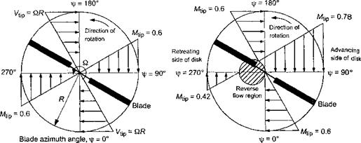
The lifting capability of any part of a rotating blade is related to its local angle of attack (AoA) and local dynamic pressure. The blade position can be defined in terms of an azimuth angle, т/г, which is defined as zero when the blade is pointing downstream, as shown in Fig. 2.1. In hovering flight, Fig. 2.1(a) shows that the velocity variation along the blade is azimuthally axisymmetric and radially linear, with zero flow velocity at the rotational axis and the velocity reaching a maximum, Vtjp, at the blade tip. The local dynamic pressure at any blade element is proportional to the square of the distance from the rotational axis. Based on elementary considerations, for a constant blade AoA, the average rotor thrust will depend on the square of the rotor tip speed, Vtip = fi/?, that is Г a Vj? . Also, the rotor power, P, will depend on the cube of the tip speed, that is P oc VJ_ (see Question 2.1),
In forward flight, a component of the free stream, Voo> adds to or subtracts from the rotational velocity at each part of the blade, that is, Viip now becomes QR+Yqq sin ifs. As shown by Fig. 2.1(b), while the distribution of velocity along the blade remains linear, it is no longer axisymmetric and varies in magnitude with respect to blade azimuth angle. It will also be evident that forward flight speed, blade pitch angle and any blade flapping, as well as the distribution of induced inflow through the rotor, will all affect the blade section AoA and, therefore, the blade lift distribution, rotor thrust, and rotor power consumption. This nonuniformity of the AoA over the rotor disk is the complication with the helicopter rotor that makes its aerodynamic analysis difficult.
|
I Vx= 0.3 QR
(a) Hovering flight (b) Forward flight, ц = 0.3 Figure 2.1 Distribution of incident velocity normal to the leading edge of the rotor blade, (a) Hovering flight, (b) Forward flight at /t = 0.3. |
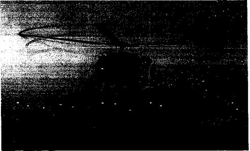
Unlike on a fixed-wing, which has a relatively uniform lift loading over its span, the high dynamic pressure found at the tips of a helicopter blade produces a concentration of aerodynamic forces there. As a consequence, strong vortices form and trail from each blade tip. Figure 2.2 shows an example of the physical nature of the vortical wake generated by a helicopter rotor in hovering flight (see also Figs. 1.38,10.1, and 10.2). Here, the blade tip vortices are rendered visible by natural condensation of water vapor in the
|
Figure 2.2 Hovering helicopter showing the vortical rotor wake through natural condensation of water vapor inside the tip vortex cores. (Courtesy of the US Navy, Patuxent River Navel Air Station.) |
air. These vapor trails are only obtained under conditions when the air temperature is close to the dew point; it is produced by the small amount of cooling that takes place inside the low pressure vortex cores. It will be seen that the vortices are convected downward below the rotor and form a series of interlocking, almost helical trajectories. For the most part, the net flow velocity at the plane of the rotor and in the rotor wake itself is comprised of the velocities induced by these tip vortices. For this reason, predicting the strengths and locations of the tip vortices (see Chapter 10) plays an important role in determining blade airloads and rotor performance, as well as in designing the blades and rotor as a system.
All helicopters spend considerable time in hover, which is a flight condition where they are specifically designed to be operationally efficient. In hover, the main purposes of the rotor are to provide a vertical lifting force in opposition to the weight of the helicopter and flight control. However, in forward flight the rotor must also provide a propulsive and force to overcome the drag of the helicopter. This is obtained by tilting the plane of the rotor forward, while increasing the overall rotor thrust so that that the vertical component of thrust (lift) remains equal to the aircraft weight. In forward flight the rotor blades encounter an asymmetric velocity field, which is a maximum on the blade that advances into the relative wind and a minimum on the blade that retreats away from the relative wind [see Fig. 2.1(b)], The local dynamic pressure and the blade airloads, therefore, become periodic primarily at the rotational speed of the rotor (i. e., once per revolution or 1/rev). Because of the articulation built into helicopter blade designs, the rotor blades will begin to flap about their hinges causing the rotor disk to tilt. This inherent tendency can be compensated for by the pilot by using appropriate cyclic pitch inputs to the blades. This changes the magnitude and phasing of the 1/rev aerodynamic lift forces over the disk, and so it can be used to maintain a desirable orientation of the rotor disk to meet propulsion and flight control requirements. The inherent coupling among blade pitch inputs, the aerodynamic forces and the blade flapping response is discussed in detail in Chapter 4.
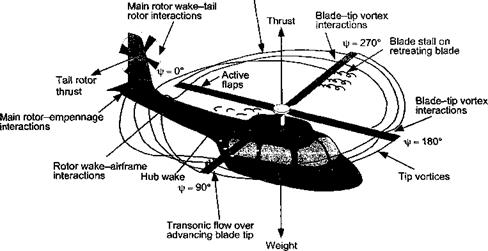
The overall aerodynamic complexity of the helicopter in forward flight can be appreciated from Fig. 2.3. The flow field in which the rotor operates is considerably more complex
|
Complex vortex wake structure
Figure 2.3 Schematic showing the flow structure and some aerodynamic problem areas on a helicopter in forward flight. |
than that of a fixed-wing aircraft, mainly because of the individual wakes trailed from each blade. For a fixed-wing aircraft, the wing wake and tip vortices trail downstream of the aircraft. However, for a helicopter in forward flight, the blade tip vortices can remain close to the rotor and to following blades for several rotor revolutions. As a result of the low disk loading (thrust carried per unit area of the rotor disk) and generally low average flow velocity through the rotor disk, these vortices remain close enough to produce a strongly three-dimensional induced velocity field. As following blades encounter this induced velocity field, fluctuating airloads are produced on the blades.[10] Besides affecting the rotor performance, these time-varying airloads can be a source of high rotor vibrations and strongly focused obtrusive noise.
At higher forward flight speeds, the inherently asymmetric nature of the flow over the rotor disk gives rise to a number of aerodynamic problems that ultimately limit the rotor performance. The most obvious is that the blade tips on the advancing side of the rotor disk can start to penetrate into supercritical and transonic flow regimes, with the associated formation of compressibility zones and, ultimately, strong shock waves. In addition to the occurrence of wave drag and the possibilities of shock induced flow separation, both phenomena require much more power to drive the rotor, the periodic formation of shock waves is another source of obtrusive noise. The increased power demands placed on the rotor system, when compressibility effects manifest, will eventually limit forward flight speeds. Although compressibility effects on contemporary rotors can be relieved to some extent by the use of swept tip blades and thin “transonic” airfoils, the problems of increased power requirements and noise are only delayed to moderately higher forward flight speeds and are not eliminated.
On the retreating side of the disk, that is, where the blades are retreating away from the relative wind because of the forward night velocity of the helicopter, the local velocity and dynamic pressure at the blade are relatively low and the blades are required to operate at higher AoA to maintain lift. If these values of AoA become too large, then the retreating blade will stall. This results in a loss of overall lifting and propulsive capability from the rotor and sets an intrinsic barrier to further increases in forward flight speed. It is interesting to note that while stall on a fixed-wing aircraft occurs at low flight speeds, a helicopter encounters the problem of stall at relatively high flight speeds. Because of the inherent time-dependent nature of the flow environment on the rotor blades in forward flight, retreating blade stall is highly unsteady in nature and is referred to as dynamic stall (see Chapter 9). The unsteady airloads produced during dynamic stall are an additional source of vibration on the helicopter, which can significantly limit its forward flight and maneuvering capability. The various aerodynamic interactions that can exist between the rotor wake and the airframe, including the tail rotor and empennage, are also worthy of note (see Fig. 2.3). Although fundamentally complicated, these interactions can lead to various significant aerodynamic interference effects that cannot be ignored in the design of the helicopter. These issues are discussed in Chapter lx.


