The Flight Environment
Hypersonic flight either of space-transportation systems or of hypersonic aircraft in the Earth atmosphere is in the focal point of the book. Hence the flight environment considered here is that which the Earth atmosphere poses. The basic features and properties are discussed, and references are given for detailed information.
2.1 The Earth Atmosphere
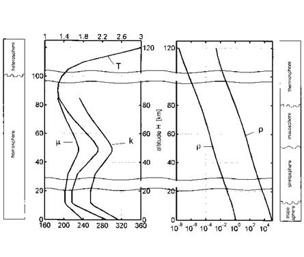
The Earth atmosphere consists of several layers, the troposphere from sea level up to approximately 10 km, the stratosphere between 10 km and 50 km, the mesosphere between 50 km and 80 km, and the thermosphere above approximately 80 km altitude, Fig. 2.1. The weather phenomena occur mainly in the troposphere, and consequently the fluctuations there mix and disperse introduced contaminants. These fluctuations are only weakly present at higher altitudes.
The stratosphere is characterized by a temperature plateau around 220230 K, in the mesosphere it becomes colder, in the thermosphere the temperature rises fast with altitude. Ecologically important is the altitude between 18 km and 25 km with the vulnerable ozone layer.
The composition of the atmosphere can be considered as constant in the homosphere up to approximately 80 km altitude with the mean molecular weight being M = 28.9644 kg/kg-mole. At 100 km altitude we have still M = 28.8674 kg/kg-mole. In the heterosphere, above 100 km altitude, it drops markedly with altitude, at 120 km the mean molecular weight is down to M = 28.0673 kg/kg-mole. This is important especially for computational simulations of aerothermodynamics. Note that also around 100 km altitude the continuum domain ends (Section 2.3).
It should be mentioned, that these numbers are average numbers, which partly depend strongly on the degree of geographical latitude of a location, and that they are changing with time (seasons, atmospheric tides, sun-spot activities). A large number of reference and standard atmosphere models is discussed in [2], where also model uncertainties and limitations are noted.
In aerothermodynamics we work usually with the U. S. standard atmosphere [3], in order to determine static pressure (p), density (p), temperature
(C Springer International Publishing Switzerland 2015 E. H. Hirschel, Basics of Aerothermodynamics,
DOI: 10.1007/978-3-319-14373-6 _2
 thermal conductivity к [102J / m s К ] dynamic viscosity p [10s N s / m2]
![]() pressure p [Pa] density p [kg / m3]
pressure p [Pa] density p [kg / m3]
Fig. 2.1. Atmospheric layers and some properties of the atmosphere as function of the altitude [1], based on [3] (see also Table 2.1).
(T) etc. as function of the altitude, Table 2.1. The 15°C standard atmosphere assumes a temperature of 15°C at sea level. A graphical view of some properties of the standard atmosphere is given in Fig. 2.1.
The pressure p decreases rapidly with increasing altitude and so does the density p. Because the temperature T does not change much, the curves of p and p look similar. The dynamic viscosity p is a function of the temperature and can be determined with the Sutherland formula, Sub-Section 4.2.2. Sutherland’s formula becomes inaccurate for the conditions present at high altitudes [3] (change of the composition of air, see above). Therefore the data are restricted to altitudes of H ^ 86 km. An empirical relation comparable to Sutherland’s formula, i. e., Hansen’s formula, Sub-Section 4.2.3, is used for the calculation of the thermal conductivity k. Again the data are restricted to altitudes of H ^ 86 km.
Uncertainties in atmospheric data influence guidance and control of a hypersonic flight vehicle. Large density fluctuations/uncertainties, which predominantly can occur at approximately 60-80 km altitude, must be compensated during, for example, a re-entry flight. Otherwise a (down) range
![The Flight Environment Подпись: Table 2.1. Properties of the 15°C U. S. standard atmosphere as function of the altitude [3]. Altitude Temperature Pressure Density Dynamic Thermal H [km] T И p [Pa] P [kg/rn] viscosity P [N s/m] conductivity к [W/m K] 0 288.150 1.013 • 105 1.225 10° 1.789 • 10~5 2.536 • 10~2 5 255.676 5.405 • 10 7.364 • 10- 1.628 • 10~5 2.276 • 10~2 10 223.252 2.650 • 104 4.135 • 10-1 1.458 • 10~5 2.009 • 10~2 20 216.650 5.529 • 103 8.891 • 10~2 1.421 • 10~5 1.953 • 10~2 30 226.509 1.197 • 103 1.841 • 10~2 1.475 • 10~5 2.036 • 10~2 40 250.350 2.871 • 102 3.996 • 10~3 1.601 • 10~5 2.233 • 10~2 50 270.650 7.978 • 101 1.027 • 10~3 1.704 • 10~5 2.397 • 10~2 60 247.021 2.196 • 101 3.097 • 10~4 1.584 • 10~5 2.206 • 10~2 70 219.585 5.221 • 10° 8.283 • 10~5 1.438 • 10~5 1.978 • 10-2 80 198.639 1.052 • 10° 1.846 • 10~5 1.321 • 10~5 1.800 • 10-2 90 186.870 1.836 • 10-1 3.416 • 10~6 100 195.080 3.201 • 10~2 5.604 • 10-7 110 240.000 7.104 • 10~3 9.708 • 10“8 120 360.000 2.538 • 10~3 2.222 • 10~8](/img/3130/image012_4.gif) |
deviation would occur.1 A 25 per cent smaller density than assumed at that altitude would lead, without correcting measures, to an approximately 100 km larger down range [4].
For in-flight tests, for instance for vehicle-parameter identification purposes, or to obtain data on aerothermodynamic or other phenomena, it is mandatory to have highly accurate instantaneous “air data” on the trajectory in order to correlate measured parameters. The air data are the thermodynamic data p, x, T, x, pco, and the vehicle speed vector vx relative to the surrounding air space. To obtain them before or during a flight is still a difficult task.
For quick estimates of properties of the atmosphere the barometric height formula for the isothermal atmosphere can be employed:
![]() P (H) _ – pH
P (H) _ – pH
p (H = 0)
Here в is a function of the temperature T* of the standard atmosphere at a chosen altitude H*:
P RT* ■ (2-2)
At sea level we have p (H = 0) = 1.013-102 kPa, g (H = 0) = 9.80665 m/s2. R is the gas constant.
For low altitudes the temperature at sea level (H* = 0) is used: T* = 288.15 K. With it one gets в = 1.186-10-4 1/m.
For high altitudes the temperature at H* = 7,000 m is used: T* = 242,55 K. With it one obtains в = 1.40845-10~4 1/m. This value is cited in [1].
Because the temperature T is assumed to be constant, the density formula reads like the pressure formula with p (H = 0) = 1.225 kg/m3:
![]() P (H) _ рн
P (H) _ рн
P(H = 0)
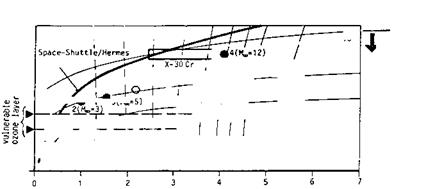
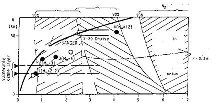
The atmosphere with its properties determines the free-stream parameters of a flight vehicle. These in turn govern the aerothermodynamic phenomena and the aerodynamic performance. We give a short overview in Figs. 2.2 to 2.4 over the main free-stream parameters and some aerothermodynamic phenomena for the altitude domain 0 km A H A 65 km, and the flight-speed domain 0 km/s A vж A 7 km/s [5]. Indicated are nominal design points of the supersonic passenger aircraft Concorde, of four reference concepts LK1 to LK4 of a German hypersonic technology study [6], of the SANGER lower stage (staging condition) [7], and of the NASP/X-30 (cruise) [8]. Typical trajectory data of re-entry vehicles (Space Shuttle Orbiter, HERMES) are included, too.
Note that the trajectories and the nominal design points in the figure reflect flight with—besides others—a dynamic pressure constraint [1]. This constraint is for the Space Shuttle Orbiter and for HERMES qж A 15 kPa. The airbreathing vehicles with ram – and/or scram-jet propulsion fly at qж = 50-90 kPa.
Fig. 2.2 shows iso-Mach-number lines. These lines are more or less parallel to iso-speed lines. Turbo propulsion is possible up to Мж « 3, i. e., vж « 1 km/s, ram-jet propulsion between 3 A Mж A 7, i. e., 1 km/s A vж A 2 km/s, and finally scram-jet propulsion between 4 A Mж A 12 to 14, i. e., 1.2 km/s A vж A 4 to 4.5 km/s [1].
Iso-unit Reynolds-number lines are at larger altitudes approximately parallel to iso-altitude lines. They show that at flight below approximately 50 km altitude boundary layers will be predominantly turbulent, Fig. 2.3, if the unit Reynolds number ReU = ржпж/рж « 105 m-1 is taken—with due reservations—as zero-order criterion. This means that the design of airbreathing flight vehicles (CAV’s/ARV’s) always has to cope with laminar-turbulent
transition and turbulence. The laminar portion at the front part of a flight vehicle will be small at small altitudes and finally will extend over the vehicle length when ReU ~ 106 m_1 is approached. On RV’s boundary layers are laminar during re-entry flight above approximately 60 km to 40 km altitude, i. e., in particular in the domain of large high-temperature real-gas effects and large thermal loads.
![The Flight Environment Подпись: Fig. 2.2. Hypersonic flight-vehicle concepts in the velocity-altitude map (v = v^) with flight Mach numbers [5] (based on [9]).](/img/3130/image015_5.gif) |
 Included in Fig. 2.3 are also lines of constant total temperature (equilibrium real gas). They indicate that with increasing speed thermal loads indeed become a major design problem of airframes of hypersonic flight vehicles, and of airbreathing propulsion systems.
Fig. 2.3. Hypersonic flight-vehicle concepts in the velocity-altitude map with flight unit Reynolds numbers (Re/L = Re^), and equilibrium real-gas total temperatures To (= Tt) [5] (based on [9]).
 Fig. 2.4 finally shows that at flight speeds below v^ ж 0.8 km/s air can be considered as a calorically and thermally perfect gas. For 0.8 km/s ^ v^ ^ 2.6 km/s vibration excitation must be taken into account. Above v^ ж 2 km/s first occurs dissociation of oxygen and then of nitrogen. The dissociation of both these major gas constituents depends strongly on the flight altitude. At altitudes below H ж 25 km we can expect in general equilibrium, above it non-equilibrium real-gas behavior. These statements are only of approximate validity, in reality the vehicle form, size, and its flight attitude play a major role.
10% 90%
![]()
sphere
v [km/sl
Fig. 2.4. Hypersonic flight-vehicle concepts in the velocity-altitude map with high – temperature real-gas effects [5] (based on [9]).
2.2 Atmospheric Properties and Models
The Earth atmosphere at the temperature of 15°C and the pressure of 101.325 kPa is a gas consisting (if dry) of molecular nitrogen (N2, 78.084 volume per cent), molecular oxygen (O2, 20.9476 volume per cent), argon (Ar, 0.934 volume per cent), carbon dioxide (CO2, 0.0314 volume per cent), and some other spurious gases [10].
For our purposes we assume for convenience that the undisturbed air consists only of the molecules N2 and O2, with all three translational, and two rotational degrees of freedom of each molecule excited, Chapter 5. During hypersonic flight in the Earth atmosphere this (model) air will be heated close to the flight vehicle due to compression and viscous effects. Consequently then first the (two) vibration degrees of freedom of the molecules become excited, and finally dissociation and recombination takes place. The gas is then a mixture of molecules and atoms. In aerothermodynamics at temperatures up to 8,000 K air can be considered as a mixture of the five species [11, 12]:
N2, N, O2, O, NO.
At high temperatures ionization may occur. Since it involves only little energy, which can be neglected in the overall flow-energy balance, we can disregard it in general. However if electromagnetic effects (radio-frequency transmission) are to be considered, we must take into account that additional species appear, see Fig. 2.5 and also, e. g., [1]:
N+, N+, O+, O+, NO+, e-.
The air, in general, can be considered as a mixture of n thermally perfect gas species [11]. This holds for the undisturbed atmosphere, and for both the external and the internal flow path of hypersonic vehicles.
For such gases it holds:
— The pressure is the sum of the partial pressures pi:
n
p = 53 Pi – (2.4)
i=1
— The density is the sum of the partial densities pi:
n
P = 53 Pi – (2.5)
i=1
— The temperature T in equilibrium is the same for all species.
—
The equation of state, with the universal gas constant R0, is
R being the gas constant of the mixture. The mass fraction ші of the species i is
— The mole fraction xi is
![]() Ci
Ci
Xi =
C
with the molar concentration Ci
|
Pi M,1 |
which has the dimension “kg-mole/m3”. The molar density of a gas mixture then is defined by
n
c = Y, Ci. (2.11)
i=1
The mean molecular weight of the undisturbed binary model air at sea level, as well as the two mass fractions, can be determined with the above eqs. (2.4) to (2.8). With the data from Table 2.1, and the molecular weights, Appendix B.1, of molecular nitrogen (MN2 = 28.02 kg/kg-mole), and molecular oxygen (Mo2 = 32 kg/kg-mole), we obtain uN2 = 0.73784, &o2 = 0.26216, and Mair = 28.9644 kg/kg-mole.
For this model air we can determine the composition in volume per cent (volume fraction ri), which is slightly different from that quoted above, since the spurious gases are now neglected. Defining the fractional density p* by
the volume fractions of nitrogen and oxygen read
and
The volume fractions are finally rN2 = 0.7627 (76.27 volume per cent), and rO2 = 0.2373 (23.73 volume per cent).
The actual “equilibrium” composition of a mixture of thermally perfect gases is always a function of the temperature and the density or the pressure. Fig. 2.5, [11], gives an example.
At large pressures and low temperatures van-der-Waals effects can occur. In flight they usually can be neglected, but in hypersonic ground-simulation facilities, especially in high-pressure/high-Reynolds number facilities they can play a non-negligible role. In Section 5.1 we come back to the van-der-Waals effects.


