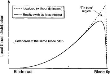
Induced Tip Loss
The formation of a trailed vortex at the tip of each blade produces a high local inflow over the tip region and effectively reduces the lifting capability there. This physical effect is shown in Fig. 2.11 in terms of the thrust distribution over the blade when compared at the same collective pitch (not at the same thrust). This phenomenon is often referred to as a tip loss, in that it represents a loss in lift relative to the finite value of lift that would
![]()
|
otherwise be produced without the influence of any tip vortices in the flow (i. e., a 2-D assumption).
In performance or preliminary rotor design work, a simple tip-loss factor В can be used to account for this physical effect such that the product BR corresponds to an effective blade radius, Re < R. A tip loss essentially corresponds to a reduction in the rotor disk area by a factor B2, that is
Ae = nR2 = n(BR)2 = B2(jxR2) = B2A. (2.51)
By a simple extension of this concept, the effect of the root cut out (essentially the inner, nonaerodynamic portion of the blade with retention and pitch attachments) can be estimated. If ro is the nondimensional radius of the root cut-out, then the effective area of the hovering rotor for momentum theory purposes becomes
Ae = 7tB2R2 – TirlR2, (2.52)
or in terms of an area ratio
![]() Ae tcB2R2 —nr^R2 2 2
Ae tcB2R2 —nr^R2 2 2
~A= ttR2 =B ~Г°’
Therefore, it will be apparent that this loss effect will manifest as a higher effective disk loading (i. e., T j Ae instead of T/A) and an increase in the average induced velocity by a factor B~x for a given thrust, with a corresponding increase in induced power.
This is also the essence of Prandtl’s approach to modeling tip-loss effects, where an analogy was made between the helical vortex wake below the rotor and a system of parallel vortex sheets – see exposition by Glauert (1935). Prandtl showed that when accounting for the tip loss, the effective blade radius, Re, is given by
where Nb is the number of blades. For helicopter rotors А,- is typically less than 0.07; thus kj will be small and the preceding equation can be simplified to
A more general tip-loss equation is sometimes used where
and where the inflow ratio is A = (Vc + u,)/ £25 and Vc is the climb velocity. For hovering flight with the assumption of uniform inflow it has already been shown that
![]() (2.57)
(2.57)
so that the tip-loss factor is approximated by
A graph of this result is shown in Fig. 2.12, where the factor В is shown to decrease with decreasing number of blades and also with increasing rotor thrust. The former effect results from blade-to-blade interference, whereas the latter effect has its origin in the spacing of the vortex sheets below the rotor (helical pitch of the wake). In practice, values of В for helicopter rotors are found to range from about 0.95 to 0.98, depending on the number of blades.
Gessow & Myers (1952) suggest an empirical tip-loss factor based on blade geometry alone where
![]()
![]()
 |
(2.59)
and where c is the tip chord, although it would seem that this result is not general enough to deal with other than rectangular blade tips. Sissingh (1939) has proposed the alternative geometric expression
where Co is the root chord of the main blade and г,- is the blade taper ratio (i. e., the ratio of the tip chord to the root chord). The need to determine В by one of these equations can, however, be avoided if a more general numerical approach to solving for tip-loss effects is used (see Section 3.2.4).


