Local Analysis of Radiation Cooling
For the following simple analysis it is assumed that the continuum approach is valid (for a general introduction to energy transport by thermal radiation see, e. g., E. R.G. Eckert et al. [16], R. B. Bird et al. [17]). Slip effects as well as high-temperature real-gas effects are not regarded. Non-convex effects will be treated later, Sub-Section 3.2.5.
The basic assumption is that of a locally one-dimensional heat-transfer mechanism (see the situation given in Fig. 3.1). This implies the neglect of
changes of the thermal state of the surface in directions tangential to the vehicle surface at the location under consideration. It implies in particular that heat radiation is directed locally normal to and away from the vehicle surface.
The general balance of the heat fluxes vectors is
q — q — q =0. (3.12)
—w —gw —rad, 4 7
Case 1 of the discussion at the end of the preceding section is now the point of departure for our analysis. With the heat flux radiated away from the surface
qrad = £&T4w , (3.13)
where є is the emissivity coefficient (0 А є A 1), and a the Stefan-Boltzmann constant, Appendix B.1, we find
qw qgw V qrad b q |ш V ь(тТ |ш, (3.14)
with kw being the thermal conductivity at the wall, and y the direction normal to the surface.
A finite difference is introduced for the derivative of T, with A being a characteristic length normal to the surface of the boundary layer, i. e., a characteristic boundary-layer thickness [18], and Tr the recovery temperature of the problem. After re-arrangement we find
![]() k T T
k T T
rpA ^ n, w ± r,, _ 1 ra. s
га~єаА[ Tr >’
Since we wish to identify basic properties only in a qualitative way, we introduce for A simple proportionality relations for two-dimensional flow.
|
1 (Pr, xRe, XiX)0-5 |
For laminar flow A is assumed to be the thickness 5T of the thermal boundary layer, which we introduce with the lowest-order ansatz, the flat plate (Blasius) boundary layer with reference-temperature extension [19] to compressible flow, eq. (7.100) in Sub-Section 7.2.1:
where Pe^x, Pr^,ReXJ}X are the free-stream Peclet number, the Prandtl number and the Reynolds number, respectively. T* is the reference temperature, eq. (7.62), and the exponent of a viscosity power law, eq. (4.14) or eq. (4.15).
For turbulent flow the thickness of the viscous sub-layer is the relevant thickness, Sub-Section 7.2.1: A = Svs. We use here, however, the turbulent scaling thickness Ssc, eq. (7.106), also with reference-temperature extension
We omit now the proportionalities to constant or not strongly varying parameters, assume T* « Tra, and introduce from Section 4.2 the power-law relation for the thermal conductivity: kw ж T/fk, eq. (4.22). With = шь2 = 0.75, and шM = шМ2 = 0.65, eq. (4.15), we see that for laminar flow kw and Tra5(1+lJ^ approximately cancel each other out.
The resulting equations are to be used to explain basic properties of radiation-cooled surfaces, but also to scale the radiation-adiabatic temperature, Sub-Section 3.2.6. Therefore we write for more generality the Reynolds number in terms of reference data: Reref, L = prefuref L/^ref. For CAV’s (slender vehicles flying at low angles of attack) the free-stream data ‘TO’ can be taken as reference data. For RV’s (blunt vehicles flying at large angle of attack), boundary-layer edge data would be the proper choice.
For laminar boundary-layer flow we obtain
If Tra ^ Tr, the equations can be simplified further. We show this only for laminar flow, eq. (3.20):
For turbulent boundary layers we obtain in a similar way, however by assuming for a convenient later generalization of the results in eq. (3.25),
kw/(t*]18(1+и^) « Tr-°.6
and
|
rp4 1 /ті-0.6 (Д-еге/,ь) ‘8 1 rp г-, є ro (x/L)0-2 L r[ |
![]()
![]()
rp4 rp-0.6^£ref) 1 rp _ Tra S
Є r“ (x/L)0-2 L°-2 rl Tr ‘
Of course also these equations can be further simplified, if Tra Eqs. (3.20) and (3.23) are combined to yield
rp4 1 rp2n—l (R’Cref,!,)1 П 1 rp (-і _ Tra,
ro є ro (ж/L)" L rl Tr h
with n = 0.5 for laminar flow, and n = 0.2 for turbulent flow. This can be done for eqs. (3.21), (3.22), and (3.24), too.
It can be argued to employ in the above eqs. (3.20) to (3.25) the total temperature Tt instead of the recovery temperature Tr. However, only using the latter yields, in the frame of the chosen formulation, the expected limiting properties:
(3.26)
With our simple approximations and proportionalities, eqs. (3.15) to (3.25), we find now the qualitative result that the radiation-adiabatic wall temperature Tra on a flat surface approximately
is inversely proportional to the surface emissivity: є 0 25, is inversely proportional to the characteristic boundary-layer thickness A-0’25, with A being either the thickness of the thermal boundary-layer (ST ~ 5fiow), if the flow is laminar, or the turbulent scaling thickness (5sc), if the flow is turbulent,
is proportional to the recovery temperature Tr0 25, and with that in perfect – gas flow proportional to M°.5,
falls with laminar flow with increasing running length: (x/L)-0’125, which is a result, that M. J. Lighthill gave in 1950 [20],
falls with turbulent flow much less strongly with increasing running length:
(x/L)-0’05,
![]()

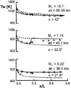
[24], of which a selection is given in Fig. 3.3. The appropriateness of the radiation-adiabatic surface as approximation of reality is also supported by these results, at least for RV’s with a thermal protection system like the Space Shuttle Orbiter has.
|
Fig. 3.3. The radiation-adiabatic temperature (Tw = Tra) along the windward center line of the Space Shuttle Orbiter [24]. Computed data: M= 15.7: – – – fully catalytic surface, • • • non-catalytic surface, — partially catalytic surface, Mx = 7.74 and Mx = 5.22: – – – fully turbulent, • • • fully laminar, — with transition. Space Shuttle Orbiter flight data: o. |
The computations with a coupled Euler/boundary-layer method were made with the laminar-turbulent transition locations taken from flight data, and a surface-emissivity coefficient є = 0.85. Despite the scatter of the flight data in the transition region for M^ = 7.74, we see a rather good agreement of computed and flight data. At the large Mach number the flow is fully laminar, surface catalytic recombination appears to be small. At the two lower Mach numbers surface catalytic recombination does not play a role, the flow is more or less in thermo-chemical equilibrium, Chapter 5.
We clearly see for the two smaller flight Mach numbers that the radiation – adiabatic temperature Tra drops much faster for laminar than for turbulent flow, and that indeed behind the transition location Traturb is appreciably larger than Traiam. The level of Tra depends distinctly on the flight Mach number, being highest for the largest Mach number. It should be remembered, that it also depends on the boundary-layer’s unit edge Reynolds number, which depends on both the flight altitude and the angle of attack.
Not shown here are the results from [24] regarding the pressure and the skin-friction coefficient. The former is rather insensitive to both surface catalytic recombination and the state (laminar or turbulent) of the boundary layer. The latter at large Mach numbers reacts weakly on surface catalytic recombination, but at lower Mach numbers, i. e., lower altitudes, strongly on the state of the boundary layer, laminar or turbulent, like the radiation-adiabatic temperature.
Fig. 3.3 tells us also, with all caution, that the radiation-adiabatic surface obviously is a not too bad approximation of reality, at least for the type of thermal protection system employed on the Space Shuttle Orbiter. The measured and the computed temperatures are very close to each other, hence the heat flux into the wall qw must be small.
It has not yet been quantified, how the thermal state of the surface evolves during an actual re-entry flight. It is to be surmised that a weak thermal reversal sets in after the peak heating in approximately 70 km altitude has occurred, page 43. The properties of the TPS, heat conduction—depending on temperature and pressure in the case of the Space Shuttle Orbiter [25]—, and heat capacity, in sum the thermal inertia of the TPS, will play a role. In any case, the thermal reversal appears to be small on a large part of the trajectory. Probably it is becoming large only on the low-speed segment of the latter.
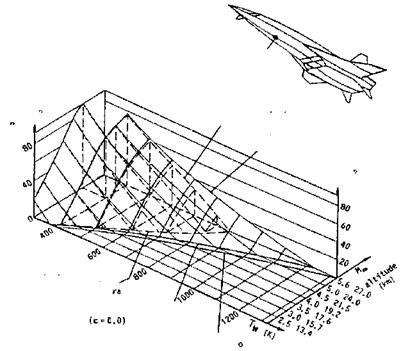
Less is known today regarding airbreathing CAV’s. To get a feeling for the involved heat fluxes and temperatures consider the example in Fig. 3.4, which, however, covers only a small and low Mach number flight span [26].
We look first at the M^-Tw surface at qw =0. The recovery temperature is smaller everywhere than the total temperature. Radiation cooling reduces the temperature at M= 5.6 by approximately 350 K compared to the recovery temperature. At smaller flight Mach numbers, and hence flight altitudes, the radiation cooling loses fast its effectiveness. This is due to the high unit Reynolds numbers, Fig. 2.3, which reduce the boundary layer thickness.
Look now at the qw-Tw surface at M= 5.6. To sustain a wall temperature of, for instance, Tw = 1,000 K, a heat flux into the wall of qw « 14 kW/m2 would be necessary without radiation cooling. With radiation cooling the temperature would anyway only be Tra « 870 K. Assume now an actual heat flux into the wall of qw « 10 kW/m2. This is approximately 27 per cent of the radiation heat flux qrad in the case of the radiation-adiabatic surface. This in per cent not so small actual heat flux reduces the wall temperature compared to the radiation adiabatic temperature by AT « 70 K.
We have seen above that the radiation-adiabatic temperature under certain conditions is a conservative estimation of the wall temperature, and that the actual temperature will lie close to it, Tw « Tra. Coupled flow-structure analyses, for instance show, that this in general is true, see, e. g., [27, 28]. We have mentioned above the likelihood of a thermal reversal, and add that also with internal heat transfer mechanisms, for instance transverse radiation cooling through the structure of a control surface to the leeward side of it,
 data point
qw with radiation
qw without radiation
qw{KW/nrO
radiation adiabatic wall temperature T
U »G,85)
recovery temperature Tr
total temperature T
Fig. 3.4. Heat fluxes and temperatures at the lower symmetry line of a hypersonic flight vehicle at different trajectory points (flight Mach number Mю and altitude) [26]. The data point lies 5 m downstream of the vehicle nose. є = 0.85, turbulent flow, approximate method. qw is the heat flux into the wall, T0 = Tt.
[6], Tw > Tra can result. If for the quantification of a given design-critical thermal-surface effect Tra is too crude an approximation, the true Tw must be determined with a multidisciplinary ansatz [2].


