The Calculation of Flows for Well-Defined Body Shapes
The flow functions described thus far are basic functions. By combining these functions a multitude of more complicated flows can be described. When combining these functions, the velocities will add vectorially. This is obvious from Equation 2.53a, since
grad ф = grad ф + grad ф2 + • • • or
v = v, + v2+–•
As an example of the use of these functions, consider the classic
|
У
X = -1 X = 1 Figure 2.16 Source-sink combination in a uniforn^flow. |
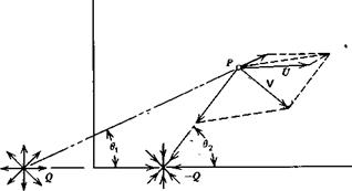
two-dimensional case illustrated in Figure 2.16. Here a source and a sink (a negative source) of equal strength are placed a unit distance from either side of the origin in a uniform flow. Three velocities from the source, sink, and uniform flow are shown added vectorially at P giving the resultant velocity, V.
It is easily verified that the entire resulting flow is symmetrical about both the x – and у-axes. To the left of the source along the x-axis a distance of ^ from the origin a stagnation point exists where the resultant velocity is zero/ The location of this point can be found from Equation 2.59 for the velocity from a source (or sink).
0 = U——- —- H————
2тг(Хо-1) 2ir(*o+l)
or
Xo2=1+47 (2.65)
7TU
It will be seen that this point lies on a dividing streamline that is closed and that separates the flow leaving the source and entering the sink from the uniform flow. The resultant streamline pattern can be constructed by- calculating the velocity at many points in the field and fairing streamlines tangent to these vectors. However, a more direct way is to form the stream function and then solve for y(x) for constant values of ф. Adding the ф functions for the uniform flow, source, and sink, one obtains
ф = ^(в1-в2)+иУ (2.66)
where в and в2 are shown in Figure 2.16. Because of the multivaluedness of the tangent function, one must be careful in evaluating this expression.
At the stagnation point, 0, = 62 and у = 0, so that ф = 0. Since this point lies on the dividing streamline, a value of ф = 0 will define this streamline. Hence
Since the flow is symmetrical, we only need to calculate the streamline shapes in one quadrant, say the one for which x and у are both positive. In this quadrant,
 У
У
l + x
-i У
2 = 7г – tan – r^—
1-х
Hence x and у along the dividing streamline are related by
tan~‘ j _I*-yi = i}~2^y) (2’68)
This can be solved explicitly for x.
Notice that as у approaches zero in Equation 2.68, x approaches the value given by Equation 2.65.
Since any streamline can be replaced by a solid boundary, the dividing streamline represents a closed body. If it is assumed that the body’s fineness ratio (i. e., thickness to length) is small, then at its maximum thickness point (x = 0), Equation 2.68 can be written approximately as
2уо=тг(і-2-^у0)
or
Уо=2[1 + (тг Ulq) (2‘70)
y0 is the semithickness of the body corresponding to x0, the semilength. Hence the fineness ratio of the body, t/l, is related to ql U by
![]() t qlU l 2[1 + (qlnU)]312
t qlU l 2[1 + (qlnU)]312
This classical body shape is referred to as the Rankine oval. The streamline pattern can be determined as a function of the streamline position far from the body. If y„ is the location of a particular streamline away from the body
then, for this particular streamline,
ф = у„и
Equating this to Equation 2.66, one obtains a relationship between x and у along the streamline as a function of y«, and ql U that can be solved explicitly for x.
![]() (2.72)
(2.72)
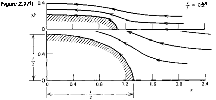
This relation was used to calculate the streamline patterns of Figure 2.17. Only the flow external to the dividing streamline is shown.
For comparison, this figure presents the streamline patterns (in one quadrant only) for 20% and 50% thick ovals. For each thickness, qlU was chosen on the basis of Equation 2.69. Because this equation assumes t/l to be small, the thickness ratio of the one shape is Slightly greater than 50%.
 |
|
Having defined the shape of a body and the velocity field around it, the next obvious point of interest is the pressure distribution over the body’s surface. In order to remove the dependence of the predicted pressure distribution on the free-stream pressure and velocity, the pressure distribution is normally presented in coefficient form, Cp, where Cp is defined according to
From Equation 2.29, Cp is found from the ratio of local velocity to free – stream velocity.
![]()
![]() (2.74)
(2.74)
Returning now to the Rankine oval, note first that Cp = 1 at the stagnation point where V is zero. Moving away from the nose along the ф = 0 streamline, the velocity increases to a maximum at some location. Depending on the fineness ratio, this point of maximum velocity may or may not be at the maximum thickness of the body; that is, x = 0.
Although one could work with ф, knowing the source (and sink) strength the easiest approach is to calculate the и and v components directly by adding the components attributed to each elementary flow function. In this case it will be found that
u_ _ q Г x + 1_______________ x — 1 1
U0 2я-І/о L(x + 1)2 + y2 (x – l)2 + y2J
_v_ = 9 Г У_______________ У 1
U0 2irU0 L(x + l)2 + y2 (jt-l)2+y2J
The pressure coefficient is then calculated from
<2J5)
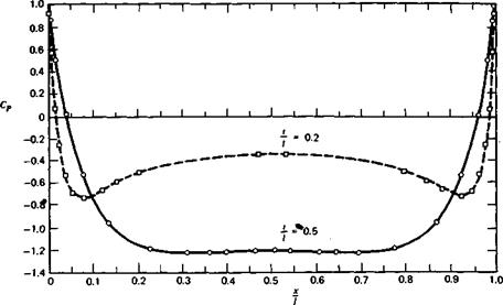
The pressure distribution along the surfaces of 20 and 50% thick Rankine ovals have been calculated using the preceding equations, and the results are presented in Figure 2.18. It is not too surprising to find that, for the 20% oval, the minimum pressure occurs near the nose, where the curvature is the greatest. For the 50% thick oval the minimum pressure occurs approximately halfway from the center of the body to the nose, but it is nearly flat over the middle 70% of the body’s length.
The Circular Cylinder
The flow field around a circular cylinder and resulting pressure distribution can be determined as a limiting case of the Rankine oval. In Figure 2.16 the source and sink were placed at x = — 1.0 and x= 1.0, respectively. We will now move them instead toward the origin, but increase their strengths in inverse proportion to the distance between them. In the limit as the distance between the source and sink goes to zero, a so-called source-sink doublet is obtained.
Letting 2e equal the distance between the source and sink and m the
|
|
 |

 m
m
2ir x2+ y2
For ф = 0, since у is not generally zero, it follows that
![]() 2,2 m
2,2 m
X + y =
This is the equation of a circle of radius
R = {m!2-nU)m
Thus ф can be written in polar coordinates as
|
|
|
|
|
The tangential velocity along the surface of the cylinder is found from Equation 2.47 by differentiating ф with respect to r and evaluating the result at r = R. In this way ve is found to be
ve = 2U %тв (2.77)
The pressure coefficient distribution, from Equation 2.75, is thus predicted to be
Cp = 1 – 4 sin20 (2.78)
In Chapter Four it will be seen that Equation 2.78 agrees fairly well with experimental results over the front half of the cylinder, but departs from actual measurements over the rear portion as the result of viscosity.
A point vortex of strength у can be placed at the origin without altering the streamline representing the surface of the cylinder. If this is done, Equation 2.77 becomes
ve = 2U sin 0 + 2%r (2.79)
Relative to po the pressure on the surface of the cylinder will be
P-p0 = ^pt/2-|p J21/ sin 0 + 2^jrf| (2.80)
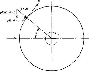
Referring to Figure 2.19, the net vertical force, or lift, on the cylinder resulting from the pressure distribution will be
L = — I pR sin в d6 Jo
|
Figure 2.19 Circular cylinder with circulation. |
or, from Equation 2.78, this reduces to
![]() L = pUy
L = pUy
This is referred to as the Kutta-Joukowski law. Although derived here specifically for a circular cylinder, it can be applied to other shapes where у represents generally the circulation around the shape. This will be amplified further in Chapter Three.
The net horizontal force, or drag, on the cylinder is found from
Using Equation 2.80, the drag is found to be zero, a result that is true in general for a closed body in steady potential flow. This result is known as D’Alembert’s paradox, after Jean le Rond D’Alembert, a French mathematician who first reached this conclusion around 1743.


