The Numerical Calculation of Potential Flow Around Arbitrary Body Shapes
The preceding has demonstrated how particular body shapes can be generated by the superposition of elementary flow functions. This procedure can be generalized and the inverse problem can be solved where the body shape is prescribed and the elementary flow functions that will generate the body shape are found.
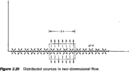
The concept of a point source or a point vortex can be extended to a continuous distribution of these functions. Consider first the two-dimensional source distribution shown in Figure 2.20. Here q is the source strength per unit length.
Consider the closed contour shown dashed in Figure 2.20, having a length of Дх and a vanishing small height. The total flux through this surface must equal q Дх. Close to the surface the и velocity components from the elemental sources will cancel so that only a v component remains. Thus
2v Дх = q Дх
or
![]() (2.82)
(2.82)
In Reference 2.4 this relationship is used to determine the flow about arbitrary shapes. Thus, unlike the Rankine oval, the body shape is specified, and the problem is to find the distribution of singularities to satisfy the condition that the velocity everywhere normal to the body surface to be zero. This particular problem is referred to as the Neumann problem. Essentially the numerical solution of the problem proceeds by segmenting the body
surface and distributing a unit source strength, q„ over the ith element. The normal velocity induced at the middle of the ith element by q> is obtained immediately from Equation 2.82. The contribution to the velocity at the ith element from another element is calculated by assuming the total source strength at the second element to be a point source located at the middle of that element. Taking n elements and letting і = 1,2, 3,…, n leads to a set of n linear simultaneous algebraic equations for the unknowns, qu q2, q3,…, q„.
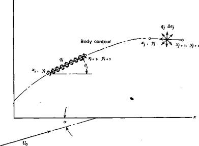
Consider in more detail this approach for two-dimensional flow. Figure 2.21 shows two elements along the surface of a body. The ith element is the control element over which the unit source strength q, is distributed. At the Jth element a point source is located having a strength equal to q; ASh ASj being the length of the /th element. The free-stream velocity U0 is shown relative to the body x-axis at an angle of attack of a.
At the center of the ith element the normal velocity components from each source and the free stream must vanish. Hence
a N
U0 sin (0, – a) = t + 2 4fn І * і (2.83)
Z j = i
Сц is an influence coefficient, which accounts for the geometry of the body shape in determining the normal velocity induced at the ith element by the source at the jth element.
If £ and t)j correspond to the midpoints of the ith element then, for Figure
2.21:
![]()
 |
_ sin (fl, – фц)
" 2тгг„
|
У
Figure 2.21 Numerical solution of the Neumann problem by a distribution of sources. |
|
гц = [(£ – Cif + Ы ~ Vi)2]m |
(2.84 b) |
|
<Pij tail у у ьі ьі |
(2.84c) |
|
0;-tan-‘yi+1-* |
(2.84 d) |
|
Хі+і ~ Xi |
|
|
£ = ^ (Xi + x/+i) |
(2.84c) |
|
Vi = (Уі + Ум) |
(2.84/) |
Having thus determined the source strengths, the resultant velocity at any location can be determined by adding vectorially the free-stream velocity to the contributions from all of the sources. Finally, the pressure distribution can be determined from Equation 2.74.
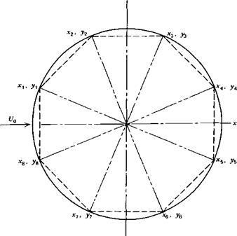
This numerical procedure applied to a circular cylinder with a unit radius is illustrated in Figure 2.22. Here, only eight elements are shown. For this case,
Xi = cos dj. y, = sin 0,
|
У
Figure 2.22 Approximation to a circular cylinder with straight-line segments. |
|
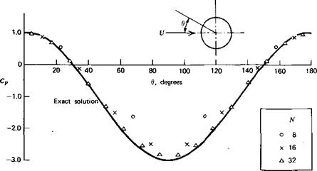
Figure 2.23 Convergence of the numerical result to the exact solution for a circular cylinder. |
where
|
n = 8 |
The numerical calculation of the pressure distribution around a circular cylinder is compared in Figure 2.23 with the exact solution given by Equation 2.78. As the number of segments increases, the approximate solution is seen to approach the exact solution rapidly. In Chapter Three this numerical method will be extended to include distributed vortices in addition to sources. In this way the lift of an arbitrary airfoil can be predicted.


