A Family of Profiles with Minimum Pressure Gradient
The Society of Automotive Engineering (SAE) organizes every year a collegiate design competition which encourages the students to design, build and fly a remote controlled model airplane, capable of carrying a maximum payload, and that can takeoff within 200 ft from a start line, make four-900 turns, touch down and roll within 400 ft from a prescribed line. Besides these take-off and landing constraints, other requirements are imposed such as not losing parts at any time during the run, using an unmodified specified gas engine with provided fuel, as well as some geometric constraints that vary from year to year (imposed maximum span or maximum surface area of the lifting elements, etc.)
From these rules, it is clear that one would like to use a wing profile having high lift capabilities Cimax. Indeed, assuming that the best propeller has been chosen for the engine during the acceleration phase on the ground, the velocity is primarily governed by the total airplane weight. In order for the airplane to rotate and take-off with a maximum payload, a high lift coefficient is needed.
From the thin airfoil theory and inviscid flow view point, all airfoils are equivalent in the sense of being capable of giving a Ci value
![]() (3.94)
(3.94)
by a combination of interchangeable incidence and camber. Of course, in reality, viscous effects at a given Reynolds number, will limit the maximum lift coefficient to a value that depends on the airfoil camber and thickness distributions. The problem of optimization seems therefore irrelevant, unless one accounts for viscous effects. One idea is to try to minimize the negative impact of viscosity by searching for the profile that will create the “least disturbance” to an inviscid flow.
Potential flows have been shown to minimize the integral of pressure over the domain surrounding the profile (Bateman principle), i. e. to minimize
where Q represents the domain of the flow.
Here we propose to minimize the integral of the pressure gradient
![]()
![]() (3.96)
(3.96)
with the understanding, as will be seen in a later chapter, that very large negative pressure gradients increase shear stress and friction drag, whereas very large positive pressure gradients trigger boundary-layer separation and pressure drag. Using the small perturbation assumption p(x, z) = рж — pUu, the integral can be written as
![]() (3.97)
(3.97)
The square of the first derivatives can be replaced by the equivalent expression, say for the x-derivative
![]() /du 2 d ( du d2u
/du 2 d ( du d2u
dx dx dx U dx2
 |
|
and similarly for the z-derivative, so that the integral becomes
The last term vanishes because u, like w, ф and ф are solution of Laplace equation. The divergence theorem is applied to the first term and results in a contour integral that vanishes at infinity, but contributes on the profile contour to the term
![]() (3.100)
(3.100)
дії is the profile boundary. dl = (dx, dz) represents an element tangent to the profile surface in the clockwise contour integral and the normal element ndl = (dz, —dx) points into the profile. Making use of the two governing PDEs, the integral can be written as
![]()
![]()
![]() dw
dw
u dx
on dx
Now, we can use the following expressions for u and w on the upper and lower surfaces
![]() , Г'(х) Г'(х)
, Г'(х) Г'(х)
u+(x) = ue(x) + 2 , u (x) = ue(x) – 2 (3.102)
і e'(x) e'(x)
w+(x) = wd(x) + U, w (x) = wd(x) – U (3.103)
|
dx — [1]e + Id |
where ue (x) represents the horizontal component of velocity induced by the distribution of sources and sinks (thickness problem) and wd (x) is the vertical component induced by the vorticity distribution (lifting problem). Replacing the contour integral by a simple integral from zero to c, substituting the above expressions and after some simplification, one gets
This result indicates that the minimization problem can also be decomposed into symmetric (Ie) and lifting (Id) problems.
The symmetric problem reads
We will proceed as was done for the lifting problem. Let
e'[x(t)] = 2{£01^ +£1 En sinnt] 0 < t < n x (t) = 2 (1 — cos t) ’
Note that we have kept a singular term which tends to infinity as t ^ 0 (i. e. x ^ 0). The behavior near the leading edge is
which corresponds to a parabolic blunt nose. The trailing edge is cusped. The horizontal velocity component is
which is the Quasi-Joukowski thickness distribution, with E0
|
e'[x (t )] = 2E0 – 2sint sin t Upon integration, the thickness distribution is obtained e[x(t)] = E0c sin t (1 + cos t) = 4E0c^^ ^1 – ^ 2 |
![]()
 |
Adding an extra term, mode 2, with E2 = — | E0 produces a profile with a far – forward maximum thickness
which is the third thickness distribution introduced earlier, with E0 = f.
With the lifting problem, we will assume that the leading edge is adapted, since we remarked that a singular leading edge will not behave well in presence of viscous effects and will probably trigger separation, Chattot [2]. Proceeding as was done earlier in the chapter, we let
O
Гr[x(t)] = 2^ 22 An sin nt (3.114)
n=1
using only regular terms in the series, which means that the flat plate is not an element of this family. Hence we have
to
wd (x) = U^^An cos nt (3.115)
n=1
After some algebra one gets in this case
TO
Id = nAl (3.116)
n=1
Keeping, for example, only the first mode results in the parabolic cambered plate at zero incidence, Fig. 3.17.
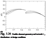
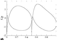
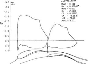
More interesting results have been obtained with this approach in the design of multiple element airfoil camberlines. For instance, a double element airfoil can be designed for minimum pressure gradient and a given high lift coefficient, say Ci = 2.3. A number of design parameters have to be chosen: the relative length of each element, the gap width between the two elements. Here we used a 50-50 chord percentage for each element as overlap was not advantageous with the SAE rules. The inviscid result indicates that the first element has Cl1 = 1.145 and the second element C12 = 1.155. See Fig. 3.24 for the profile geometry where 12% thickness distributions have been added to the camberline design. The inviscid Cp distributions are also shown. The gap width was set by analyzing several designs with a viscous code, MSES for multiple element airfoils by Drela [3] and selecting the best result. The final design geometry and Cp distributions are shown in Fig. 3.25. Note that the second element thickness was reduced to 7 % as it was found that the stagnation point was not moving with incidence, whereas the thickness of the first element was increased to 17 % to allow for large displacements of the leading element stagnation point. The maximum lift coefficient was found to be Cl = 3.1, (see Fig. 11.6).
 |
 |
A wind tunnel model of a low aspect ratio half-wing has been built with foam core and carbon fiber skin which validated the high lift capabilities of the design by comparison with the numerical model, Fig. 3.26.
 |
 |
Fig. 3.26 Double element wind tunnel test model


