Ideal Twist
Gessow (1948) showed that if Or = constant = 0tiP there is a special solution to the inflow equation in Eq. 3.62 that gives uniform inflow, that is,
0(r) = (3.63)
r
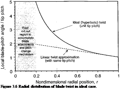
This twist distribution is called ideal twist and is shown in Fig. 3.6. This solution lays down the goal for a rotor blade design because the uniform inflow case must always correspond to the minimum induced power for the rotor when operating in hover or in axial climb. Unfortunately, the hyperbolic form of pitch angle or twist distribution given by Eq. 3.63 is physically unrealizable as r —0. However, because of the hub and root cutout, in a practical sense the blade pitch variation here does not matter anyway. Figure 3.6 shows that
 |
a linear twist distribution is reasonably close to the ideal case over the outer part of the blade.
A careful examination of airplane propellers will show that they are highly twisted and, in fact, closely conform to the ideal blade twist given by Eq. 3.63. For helicopter rotors, such high amounts of twist over the blade span is nonoptimum for the entire flight envelope. This is because the rotor must also operate in forward flight, and high values of blade twist can lead to less efficient lift and propulsion generation from the advancing side of the disk at high advance ratios. Nevertheless, because helicopters spend a substantial part of operating time in hover and low speed forward flight, there are considerable performance benefits to be realized by incorporating some blade twist.
With ideal twist the performance of the rotor can now be recalculated. If 0r = constant = #tjp, then
Using Eq. 3.13 gives X = гф = 0tip = constant, and so the preceding equation can also be written as
![]() ~ _ aC^ (a j __________ aCi„
~ _ aC^ (a j __________ aCi„
Cj — д (ytip Фйр) — ^ ^tip-
Using Eqs. 3.61 and 3.63 gives
The first term in either of the previous equations can be thought of as a mean blade pitch to produce thrust, and the second term is an additional blade-pitch angle that is required to compensate for the induced inflow produced by the generation of that thrust.
One can also prove that the ideal twist distribution gives a special result, namely a linear (triangular) lift distribution over the blade, which is consistent with uniform disk loading. Recall that the incremental thrust distribution is given by
![]() (3.68)
(3.68)
Because A is a constant, the thrust distribution on the blade varies in proportion to r (i. e., it is a linear distribution). Another way of writing the preceding equation is just
![]() (3.69)
(3.69)
Therefore, the total thrust on the rotor with ideal blade twist is
3.3.4 BEMT: Numerical Solution
In most practical applications the equations of the BEMT are solved numerically. This allows the maximum flexibility to incorporate arbitrary radial variations in twist, planform, and so on. In the numerical approach, the blade must be discretized into a series of small elements of span A r. For hovering flight, the inflow is now obtained using the discretized equation
![]() (3.71)
(3.71)
where n — 1, A is the element location (station) and rn and в{гп) are the radius and pitch angle at the mid-span of each of the N stations, respectively.[13] For climbing flight then Eq. 3.61 must be solved. When the inflow is determined using Eq. 3.71, the incremental thrust at each segment can be found using
![]() ACT„ = ^^(0(rn) r[14]n – A(r„) rn) Ar.
ACT„ = ^^(0(rn) r[14]n – A(r„) rn) Ar.
The total thrust on the rotor is then obtained by numerically integrating over the blade. The simplest approach is to use the rectangle rule, which is equivalent to considering the inflow and thrust to be constant over each segment. In this case
N
(3.73)
n=1
which will be adequate for most purposes unless only a few stations are used. The corresponding induced torque (or power) can be obtained using
![]() (3.74)
(3.74)
It is normally desirable to compare results for different rotors at the same value of Ct – Therefore, for rotors with different twist or planforms, the blade (collective) pitch, 9q, required to obtain the required value of thrust coefficient, say Ct, must be obtained iteratively starting from an assumed value for во. For this, we can use as a basis the simple relationships found previously between the blade pitch and Cj. For example, for a blade with linear twist and
or rearranging and solving for во gives
6СГ З 3 CT aC, 40tw+2V 2
l(X
Therefore, one simple iterative scheme based on a bisection method of correcting the collective pitch from iteration j to j + 1 is
starting from the initial value
Using this approach, the collective pitch is found to converge rapidly to provide the required value of Ct for any arbitrary rotor geometry, typically within two to four iterations.


