THE GENERATION OF LIFT
Lift is the component of the resultant aerodynamic forces on an airplane normal to the airplane’s velocity vector. Mostly, the lift is directed vertically upward and sustains the weight of the airplane. There are exceptions however. A jet fighter with a thrust-to-weight ratio close to unity in a steep climb may be generating very little lift with its weight being opposed mainly by the engine thrust.
The component that is the major lift producer on an airplane and on which this chapter will concentrate is the wing. Depending on the airplane’s geometry, other components can contribute to or significantly affect the lift, including the fuselage, engine nacelles, and horizontal tail. These latter components will be considered, but to a lesser extent than the wing.
WING GEOMETRY
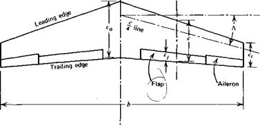
The top view, or planform, of a wing is shown in Figure 3.1. The length, b, from one wing tip to the other is defined as the wingspan. The chord, c, at some spanwise station, y, is the distance from the wing’s leading edge to its trailing edge measured parallel to the plane of symmetry in which the centerline chord, c0, lies. The chord generally varies with у so that, for purposes of characterizing wing geometry, a mean chord, c, is defined as the value that, when multiplied by the span, results in the planform area, S.
![]() (3.1)
(3.1)
The aspect ratio of a wing, A, is a measure of how long the span is with respect to the mean chord. Thus
![]() (3.2)
(3.2)
For a rectangular planform where the chord is constant, this reduces to
![]() (3.3)
(3.3)
Hof air relative to wing)
|
——— У——— Э»
Figure 3.1 Top view of a wing (planform). |
As shown in Figure 3.1, a wing planform may be tapered and swept back. The taper ratio, Л, is defined as the ratio of the tip chord, ct, to the midspan chord, c0.
A = — (3.4)
Co
The sweep angle, Л, is frequently measured relative to the quarter-chord line of the wing, that is, a line defined by the locus of points a quarter of the distance from the leading edge to the trailing edge. Л, on occasion, is also measured relative to the leading edge.
Usually the center portion of a wing is enclosed by tne fuselage. In such an instance the wing’s aspect ratio and taper ratio are determined by ignoring the?" fuselage and extrapolating the planform shape into the centerline. The midspan chord in this instance is thus somewhat fictitious. The wing root is defined as the wing section at the juncture of the wing and fuselage. Occasionally, in the literature, one will find wing geometry characterized in terms of the wing root chord instead of the midspan chord.
Approximately the aft 25 to 30% of a wing’s trailing edge is movable. On the outer one-third or so of the span the trailing edge on one side of the wing deflects opposite to that on the other. These oppositely moving surfaces are called ailerons; ailerons provide a rolling moment about the airplane’s longitudinal axis. For example, when the aileron on the left wing moves down and the one on the right moves up, a moment is produced that tends to lift the
left wing and lower the right one; this is a maneuver necessary in making a coordinated turn to the right.
The inner movable portions of the wing’s trailing edge on both sides of the wing are known as the flaps. For takeoff and landing the flaps are lowered the same on both sides. There is no differential movement of the flaps on the left and right sides of the wing. The purpose of the flaps is to allow the wing to develop a higher lift coefficient than it would otherwise. Thus, for a given weight, the airplane can fly slower with the flaps down than with them up. Flaps, including leading edge flaps and the many different types of trailing edge flaps, will be discussed in more detail later.
* For some applications both ailerons are lowered to serve as an extension
I to the flaps. In such a case they are referred to as drooped ailerons, or I flaperons. When flaperons are employed, additional roll control is usually I provided by spoilers. These are panels that project into the flow near the trailing edge to cause separation with an attendant loss of lift.
In order to understand and predict the aerodynamic behavior of a wing, it is expedient to consider first the behavior of two-dimensional airfoils. An airfoil can be thought of as a constant chord wing of infinite aspect ratio.


