Air resistance or drag
Whenever a body is moved through air, or other viscous fluid, a definite resistance to its motion is produced. In aeronautical work this resistance is usually referred to as drag.
Drag is the enemy of flight, and efforts must be made to reduce the resistance of every part of an aeroplane to a minimum, provided strength and other essential factors can be maintained. For this reason many thousands of experiments have been carried out to investigate the problems of air resistance; in fact, in this, as in almost every branch of the subject, our knowledge is founded mainly on the mean result of accumulated experimental data. Nowadays, however, there are increasingly more accurate theoretical methods of estimating drag.
Streamlines and form drag [4] [5] 2
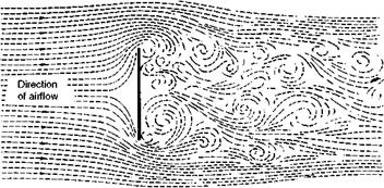
1. Form Drag. This is the portion of the resistance which is due to the fact that when a viscous fluid flows past a body, the pressure on the forward-facing part is on average higher than that on the rearward-facing portion. The extreme example of this type of resistance is a flat plate placed at right angles to the wind. The resistance is very large and almost entirely due to the pressure difference between the front and rear faces, the skin friction being negligible in comparison (Fig. 2.7).
Experiments show that not only is the pressure in front of the plate greater than the atmospheric pressure, but that the pressure behind is less than that of the atmosphere, causing a kind of ‘sucking’ effect on the plate.
|
|
Fig 2.7 Form drag
|
|
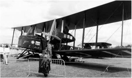
Fig 2A Parasite drag A flying replica of the Vickers Vimy bomber which was the first aeroplane to make a non-stop flight across the Atlantic (in 1919). The extensive use of bracing wires and struts creates a great deal of parasite drag.
 |
 |
Resistance, 15%
 |
Fig 2.8 Effect of streamlining
It is essential that form drag should be reduced to a minimum in all those parts of the aeroplane which are exposed to the air. This can be done by so shaping them that the flow of air past them is as smooth as possible, and much experimental work has been carried out with this in view. The results show the enormous advantage to be gained by the streamlining of all exposed parts; in fact, the figures obtained are so remarkable that they are difficult to believe without a practical demonstration. At a conservative estimate it can be said that a round tube has not much more than half the resistance of a flat plate, while if the tube is converted into the best possible streamline shape the resistance will be only one-tenth that of the round tube or one-twentieth that of the flat plate d ig – 2.8).
The streamline shapes which have given the least resistance at subsonic speeds have had a fineness ratio – i. e. alb – of between 3 and 4 (see Fig. 2.9), and the maximum value of b should be about one-third of the way back from the nose. These dimensions, however, may vary considerably without increasing the resistance to any great extent.
Fig 2B Streamlining
(By courtesy of the former British Aircraft Corporation) Concorde 002 in contrast to the Vickers Vimy of Fig. 2A
![]() AIR AND AIRFLOW – SUBSONIC SPEEDS
AIR AND AIRFLOW – SUBSONIC SPEEDS
![]()
It should be mentioned that although we now have a fair idea of the ideal shape for any separate body, it by no means follows that two bodies of this shape – e. g. a fuselage and a wing – will give the least resistance when joined together.


