Blade Design and Figure of Merit
On the basis of the predictions of profile power from the blade element analysis, the figure of merit can be written as
FM — ■ Cpid-eal , (3.129)
C pt + CPo
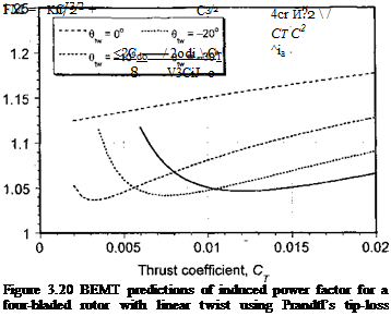
where Cpidcal = С]!21fl and Cp can be written in terms of the induced power factor, к as Cp = агС^2/л/2. From the numerical approach to the BEMT theory, and incorporating Prandtl’s tip-loss function, we can readily obtain the results for Cp, Cp0, к, and FM as a function of collective pitch or Cp, and the results can then be compared for different blade twist rates and/or planforms. It has been shown previously that blade twist primarily affects the induced power. Results showing the effects of blade twist on the induced power factor, к versus rotor thrust coefficient are given in Fig. 3.20. The values of к have been computed for a four-bladed rotor. Notice that there are significant reductions in induced power (and gains in FM) to be made by the addition of nose-down blade twist. Up to —20° of blade twist is considered optimal, with further increases in nose-down twist rate giving only minor returns within the operational values of Cj for a helicopter. The use of high blade twist rates is nonoptimal for forward flight because such blades tend to generate lower lift on the advancing blade compared to a design with less twist – see discussion in Section 6.4.5.
 |
|
The profile power also affects the FM. Using the higher-order drag variation, we have for the rotor with ideally twisted blades that
Notice that the profile power contribution to the FM is affected by the rotor solidity, cr. Therefore, it is apparent that to maximize the figure of merit the profile part of the power must be kept as low as possible, which suggests a low value of solidity. The increasing drag of the blades at higher values of Ct means the onset of stall must be delayed to high angles of attack, which means maintaining the blade loading coefficient CT/o to lower values. This requires the use of sufficient rotor solidity to maintain sectional C/’s below stall also with sufficient margins in overall Cj /or for normal flight maneuvers without rotor stall.


