Compressibility Effect: Wing Sweep
Section 3.7.1 explains the transonic effect resulting from the thickness distribution along an aircraft body. On the wing, the same phenomenon can occur, most importantly along the wing chord but altered due to the 3D wing tip influence. A local shock interacting with the boundary layer can trigger early separation, resulting in unsteady vibration and – in extreme cases – even causing the wing to stall. A typical consequence is a rapid drag increase due to the compressibility effect resulting from the transonic-flow regime. Military aircraft in hard maneuver can enter into such an undesirable situation even at a lower speed. As much as possible, designers try to
|
|
avoid, delay, or minimize the onset of flow separation over the wing due to local shocks.
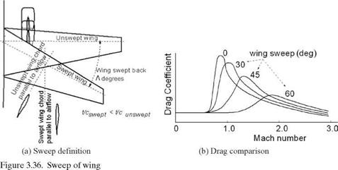
Drag divergence is a sudden increase in drag. A 20-count drag rise (CD = 0.002) at the Mach number is known as the drag divergence mach (MDD), shown in Figure 3.36b. The critical Mach (Mcrit) is the onset of the transonic-flow field and is lower than the MDD. Some texts use Mcrit with a 20-count drag increase.
Structural engineers prefer aerofoil sections to be as thick as possible, which favors structural integrity at lower weights and allows the storage of more fuel onboard. However, aerodynamicists prefer the aerofoil to be as thin as possible to minimize the transonic-flow regime in order to keep the wave drag rise lower. One way to delay the Mcrit is to sweep the wing (Figure 3.36a) either backward (see Figure 3.31, Boeing 737) or forward (see Figure 4.37e, SU47 [at www. cambridge .org/Kundu]), which thins the aerofoil t/c ratio and delays the sudden drag rise (Figure 3.36b). The former is by far more prevalent because of structural considerations. Wing slide (i. e., in which the chord length remains the same) is different from wing sweep, in which the chord length is longer by the secant of the sweep angle.
Shown here is the relationship between the sweep angle and wing geometries. The chord length of a swept wing increases, resulting in a decrease in the t/c ratio:
chordswept = (chordunswept)/CosA (3.39)
This results in:
(thickness/chordswept) < (thickness/chordunswept) (3.40)
This directly benefits the drag divergence Mach number, divided by the cosine of the sweep angle:
Л1/4;that is, Machdivj;wept = Machdiv_unswept/C°sA1/4 (341)
The sweep also degrades the Cbmax by the cosine of the sweep angle, Л^; that is:
CLmax^swept = CLmax-unswept x СтеЛ/ (3.42)
If the trailing edge can remain unswept, then flap effectiveness is less degraded due to a quarter-chord sweep.
Qualitative characteristics between the wing sweep and the t/c ratio variation are shown in Figure 3.37.
Figure 3.38 shows typical values used in various aircraft. Another effect of speed gain is a change in CLmax, as shown in Figure 3.39. For a particular wing, the ratio
of CLmax. compressible/CLmaxJncompressible decreases to approximately 0П, as shown in
Figure 3.39.
Designers require this body of information for the aerofoil selection. The choice decides the extent of wing sweep required to lower the t/c ratio to achieve the desired result (i. e., to minimize the compressible drag increase for the cruise Mach number) while also satisfying the structural requirements. To standardize drag-rise characteristics, the flow behavior is considered to be nearly incompressible up to Mcrit and can tolerate up to MDD, allowing a 20-count drag increase (ACD = 0.002).


