DESIGN OF A FLEXIBLE CONTROLLER
An observed state feedback controller is synthesized. On the one hand, the rigid closed loop poles are placed in the same way as in subsection 1.2. On the other hand, some of the flexible modes are moved into the left half plane in order to increase their damping ratio.
Following the previous subsection, the design model is built by adding the rigid and flexible models at the outputs. Actuators are then introduced at the aircraft inputs (see Figure 2.2). Second order transfer functions ————;— are finally added at the inputs, with —^ = 0.0 and
u>f = 15 rad/s. These filters increase the roll-off properties of the controller, and thus its robustness with respect to unmodeled flexible modes. Notice that the maximal frequency of the bending modes in the previous subsection is about 15 rad/s.
A state feedback controller is first synthesized for this design model. The actuators and filters poles are not to be moved. The four rigid closed loop poles are chosen as in subsection 1.2. The 6 closed loop flexible modes are chosen as:
|
Deunping |
Freq. (rad/s) |
|
З. ООе-ОІ |
7.35е+00 |
|
3.00е-01 |
7.35e+00 |
|
3.00е-01 |
8.62е+00 |
|
З. ООе-ОІ |
8.62е+00 |
|
З. ООе-01 |
1.25е+01 |
|
З. ООе-01 |
1.25е+01 |
|
2.16е-02 |
1.35е+01 |
|
2.16е-02 |
1.35е+01 |
|
5.07е-02 |
І.4ІЄ+01 |
|
5.07е-02 |
1.4ІЄ+01 |
|
З. ООе-01 |
1.43е+01 |
|
З. ООе-01 |
1.43е+01 |
 |
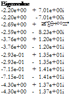
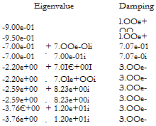
The damping ratios of the 4 critical flexible modes are increased up to 30 %. The two other flexible modes are left unchanged. Summarizing, the closed loop poles, corresponding to the state-feedback controller, are:
 Freq. (rad/s)
9.00e-01 У. rigid modes
9.50Є-01
9.90e-01
9.90e-01
7.35e+00 V, flexible modes
7.35e+00
8.62e+00
8.62e+00
1.25e+01
1.25e+01
|
-2.93e-01 |
+ |
1.35e+01i |
2.166-02 |
1.356+01 |
|
|
-2.936-01 |
– |
1.356+01І |
2.166-02 |
1.35e+01 |
|
|
-7.156-01 |
+ |
1.4І6+01І |
5.076-02 |
1.4І6+01 |
|
|
-7.156-01 |
– |
1.4І6+01І |
5.076-02 |
1.4І6+01 |
|
|
О о + ф о со 1 |
+ |
1.376+0ІІ |
З. ООе-01 |
1.436+01 |
|
|
-4.306+00 |
– |
1.37e+01i |
З. ООе-01 |
1.436+01 |
|
|
-1.056+01 |
+ |
1.076+01І |
7.006-01 |
І. БОе+01 |
‘/. filter modes |
|
-1.056+01 |
– |
1.07e+01i |
7.00в-01 |
1.506+01 |
|
|
1 »-»■ о СП ф + о |
+ |
1.076+01І |
7.00в-01 |
1.506+01 |
|
|
-1.056+01 |
– |
1.076+01І |
7.006-01 |
1.506+01 |
|
|
-1.046+01 |
l. OOe+OO |
1.046+01 |
‘/, actuator modes |
||
|
-І. Обв+01 |
l. OOe+OO |
І. Обе+ОІ |
|||
|
-3.766+01 |
l. OOe+OO |
3.766+01 |
|||
|
-3.376+01 |
+ |
3.876+01і |
б. ббе-01 |
Б. ІЗв+01 |
|
|
-3.376+01 |
– |
3.876+Oli |
6.566-01 |
5.136+01 |
An observer is now to be built. Since the states of the filters are available, the new design model is the same as the one for the state feedback, except that it does not include the filters. The observer gain places the closed loop poles roughly in the same way as the state feedback gain. When applying the observed state feedback controller to the complete aircraft model (which thus includes the rigid model, the flexible model and the actuators), the closed loop poles are classically the poles of the state – feedback controller and those of the observer.


