Our heavyweight helicopter equal in the world does not have
In Rostov started production of the most load-lifting rotary-wing car The Russian holding «Helicopt[...]

Everything about aircrafts and helicopters. News and events in aviation worldwide. Civil, transportation, military helicopters and airplanes.

Everything about aircrafts and helicopters. News and events in aviation worldwide. Civil, transportation, military helicopters and airplanes.

Everything about aircrafts and helicopters. News and events in aviation worldwide. Civil, transportation, military helicopters and airplanes.

Everything about aircrafts and helicopters. News and events in aviation worldwide. Civil, transportation, military helicopters and airplanes.


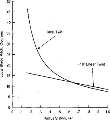
The lift on the entire blade is the integration of the lift on all the blade elements from the center of the rotor to the tip. In order to perform the integration in a tidy manner, the blade will be assumed to have ideal twist. Most helicopter blades are twisted such that the pitch at the tip is less than the pitch at the root. The most common twist is linear such that:
![]() 0 — 0O +
0 — 0O +
where 0O is the pitch that the blade would have if it extended into the center of rotation and 0г is the angle of twist or washout between the center of rotation and the tip. The value of linear twist in current use is from —5° to —16°. For blades with ideal twist instead of linear twist, the local value of pitch is:
![]() A
A
r/R where 0, is the pitch at the blade tip. Plots of blade pitch for a blade with —10 degrees of linear twist and for a blade with ideal twist are shown in Figure 1.7 for approximately the same rotor lift. It will later be shown that the ideal twist produces better rotor performance than any other type of twist, but that the margin of increased performance over linear twist is relatively small. Actual helicopter blades use linear twist instead of ideal twist because of the ease of manufacture. Because of the ease of analysis, however, ideal twist is assumed in this derivation with the consequences of linear twist shown later.
![]()
|
|||
|
|||
|
|||
|
|||
|
|||
|
|
||
|
|||
|
|||
|
|||
|
|||
|
|||
|
![]()
where AL/Ar is the lift per running foot along the blade and is simply a linear—or triangular—lift distribution with respect to blade station. The total lift on the blade is equal to the area of the triangle:
Thus the lift per blade is:
and the total rotor thrust is the lift per blade times the number of blades, b:
Note the similarity of this equation with the equation for the lift of an airplane wing:
Lw=-V2Saa
2
In the case of the rotor, (p/2)({TR)2 is the dynamic pressure based on tip speed, bcR is the total blade area, a is the slope of the airfoil lift curve, and (0, — ф,)/2 is an effective angle of attack.