Maximum Grid Expansion Ratio in the Boundary Layer Resolution
For the investigation of the near wall grid expansion the reference grid is again used as a basis. The expansion ratio was varied between r = 1.1 up to r = 2.0. Again all eight turbulence models were applied.
In the results with small variations the influence of the expansion ratio could be seen clearly. The behavior of the error prediction with different turbulence models is similar (Fig. 8). With a bigger ratio upto r = 2.0, the differences to the reference solution lead to 8% in the friction coefficients Cf in some cases. Greater values of the expansion ratio weren’t investigated. To ensure that the error prediction doesn’t depend on the local streamwise position within the boundary layer, the normalized
|
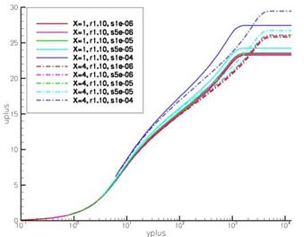
Fig. 3 Flat plate — WCX model — graph of u+ /y+ with variations of grid inclination in the boundary layer at x = 1.021 and x = 4. 124 |
|
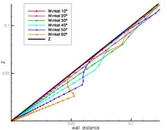
Fig. 4 Computation of the wall distance in TAU with variations of the grid inclination in the boundary layer in comparision to the correct wall distance z |
|
Fig. 5 Flat plate — influence of the grid inclination on the prediction of the friction coefficient Cf, normalized with Cf of the reference grid with SAE, SAO, Hellsten EARSM and Wilcox k-m model |
error factor of friction Cfn has been evaluated at several positions. The behaviors of Cfn over r as well as y+ were compared between these locations. As the comparison of the cfn progression reveals, the error predictions are nearly identical at all
|
Fig. 6 Flat plate — Hellsten EARSM model — graph of u+ /y+ with variations of y+ at x = 1.021 and x = 4.124 |
positions. A minimal deviation occurs only at high levels of y+ and r. According to that Cfn can be assumed independent of the stream-wise location in boundary layer.
Implementation of the Expansion Sensor
For the implementation of the sensor for the expansion ratio again the boundary layer has to be scanned. The identified maximal ratio is assumed as constant at the related surface grid point. The behavior of the error was parameterized with a polynomial 3rd order for each turbulence model. This polynomial again represents the difference to the results with the reference grid in %. The difference is set to 100% if the expansion ratio leaves the investigated range of values.


