MEANS FOR GENERATING LIFT AND. PROPULSIVE FORCES
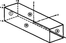
3.1 Overall lift and associated drag forces. Consider now more specifically how lift forces can be generated and what this costs in terms of energy to be expended. To begin with, the overall flow characteristics which we can already identified allow us to derive some important general relations and guidelines by the application of the momentum theorem, even without defining in detail how the lift is generated (see e. g. Th von Karman & J Burgers (1935), W R Sears (1955), В Thwaites (I960)). Consider a general lifting body of span 2s, length l, and thickness t (or volume Vol) in a uniform stream of velocity Vo. In a rectangular coordinate system fixed in the body, with x along the mainstream direction, у sideways, and z vertical, we put a large cylindrical control surface S around the body which itself is situated at the origin, as indicated in Fig. 3.1. The upstream face I lies at x = -» and the downstream face II, the so-called Trefftz plane, at x = +» (after E Trefftz (1921)). The plane sidepanels III are situated at
|
i |
z=±A ; – B<y<+B
(3.1)
у = ± В * – A<z<+A.
We have seen that the flow past a lifting body always leads to the formation
|
Fig. 3.1 Surface of integration around a lifting body at the origin |
of at least one surface of discontinuity, a vortex sheet which originates at the separation line where the flows over the upper and lower surface meet again. This trailing vortex sheet extends downstream and intersects the Trefftz plane. The shape of the trace in the Trefftz plane depends on the shape of the lifting body. Further, the body leaves a viscous wake of reduced momentum behind. In the flow past bodies with separation from sharp edges, the wake is combined with the trailing vortex sheet and thus also leaves the control surface through the Trefftz plane. If lift is generated on the body through compressions by shockwaves, the resulting entropy increase will again be felt in the Trefftz plane. This may be the whole effect if the shockwaves extend only a finite distance into the stream, as in some mixed flows at transonic speeds. At supersonic speeds, shockwaves and other disturbances will, in general, reach the sidepanels of the control surface. Thus, in principle, the flow conditions at the control surface can be determined and from these the forces acting on the body enclosed by it. These are pressure forces obtained by integrating the pressure over the surface of the body.
If the body is in steady flight and symmetrical with regard to the x, z – plane, then there is only a lift force L in the z-direction and a drag force 5 in the x-direction. According to the momentum theorem and the conservation of mass, the overall force vector is
– “ " // (P “ P0)d – ~ [/ P-K^0 + – ‘ d-^ ‘ (3.2)
S ‘s
This states that the flow of momentum through a fixed surface bounding a definite volume of fluid, together with the resultant of the pressure integral over the surface, is equal to the force exerted by the fluid on the body in it. The perturbation velocity vector ■
X – vxi + vyi + vzk (3.3)
has been introduced, with і, j, к the unit vectors along the three axes. dS is in the direction of the outward normal to the control surface. The upstream face I does not contribute to the integrals since, in the undisturbed stream, p = Pq and у = 0. On the downstream face II, dS = idydx, so that
(y0 + v)dS = (V0 + vx)dydz. (3.4)
On the horizontal parts of the sidepanels III, dS = ikdxdy, so that
(Vq + v)dS = ±vzdxdy. (3.5)
On the vertical parts of the sidepanels III, dS = ±jdxdz, so that
(V0 + v)dS = ±v dxdz. (3.6)
Inserting these relations into (3.2) and assembling the vertical and horizontal force components, we find for the lift and drag forces
+A +B
|
1 – – I j cpvz(vo+ vx>:udydz + -A – B
|
These relations can be evaluated further only if the flowfield of the lifting body is specified in more detail. Here, we want to use them to demonstrate in a special case how the lift on a threedimensional body is accompanied by a drag force, even in inviscid flow. We take the case where only a vortex sheet is left behind. This means that we do not consider viscous wakes or shockwaves and that we assume isentropic flow. At the same time, we want to demonstrate how many further assumptions and concepts must be introduced before relations can be obtained which are useful in practice.


