Mechanical model
 |
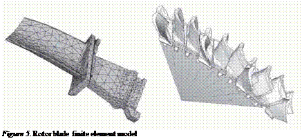
The rotor blade is represented by 3D 10-node quadratic tetrahedron finite elements with hourglass control (Fig. 5). The rotating turbine disc assembly is represented by a cyclic parabolic finite element model. Neglecting the frictional slip at the blade root due to high centrifugal stresses, the blade is rigidly attached to the rotor by a fir tree (Fig. 5). This model is used to simulate the vibration of the entire disc. All FE analyses are performed with a commercial general purpose finite element solver.
The free vibration FE analysis is performed at a rotational speed of 6957 RPM. The eigenfrequencies Д„ = ші, п/2п (where ui>n denotes angular eigen-
frequency) of the disc assembly are obtained from
([K(fi, n)] – u2i, n [M(и)]){фі, п}(1) =0 (1)
where the blade complex matrices of mass [M(n)] and stiffness [K(fi, n)] depend on nodal diameter number n = 0,1, …,N/2 for even N or (N—1)/2 if N is an odd number of blades [11]. The stiffening effect caused by the rotation is included in the matrix [K(fi, n)]. For each mode i with nodal diameter n (except for n = 0 and n = N/2), two identical eigenfrequencies {фіп }(1) are computed from Eq. 1 which correspond to two possible mode shapes of the cyclic sector.
The computed nodal diameter diagram and torsional mode shapes of interest are presented in Fig. 6. The calculated eigenfrequencies vary slightly from
|
Figure 6. Calculated torsional eigenfrequencies in the excitation region due to a stator excitation of 43 vanes |
4798.8 Hz to 4796.6 Hz for increasing nodal diameters from 20 up to 24. For 43 vanes and 63 blades, the 21st nodal diameter will be predominantly excited. From the rig test, accelerating the rotor through the resonance [4], [5], a resonance frequency at 4800 RPM was determined. The calculated eigenfrequency is in good agreement with these observations.


