Slender wings with non-planar vortex wakes
3.3 With regard to the question of how lift forces can actually be generated, we have so far identified only one basic type of flow, the classical streamline flow past aerofoils. On a threedimensional wing, this is associated with separation from the trailing edge only and the formation of a trailing vortex sheet which is nearly plane, at least initially. There are, however, other useful flows and an alternative type of flow is one where separation from side edges is an essential feature and where the trailing vortex sheet is essentially non-planar. One such flow has been shown in Fig. 2.16 where the vertical extent of the trailing vortex sheet is very pronounced because the side edges are much longer than the trailing edge on this rectangular wing of very small aspect ratio. Intuitively, one would expect that the extended non-planar vortex sheets should accelerate a greater mass of air downward and hence produce more lift than the plane vortex sheet from the trailing edge only, for the same span and angle of incidence. As we shall discuss in more detail in Section 4.6 and in Chapter 6, this turns out to be true. The lift is then a non-linear function of the angle of incidence, and (3.28) no longer applies. Also, the vortex drag for a given span and overall lift may be smaller, that is, the value of Ky can be smaller than unity in this case. In principle, then, this is another basic type of flow suitable for generating lift forces.
In practice, the particular flow shown in Fig. 2.16 does not fulfil all the requirements which would make it suitable for engineering applications. We have already seen that it responds readily to disturbances and might become asymmetrical. Therefore, we are looking for flows which produce acceptable and stable arrangements of non-planar vortex sheets. There are many of this type, all associated with so-called slender wings whose semispans s are significantly smaller than their overall lengths t. s/l = 1/4 is a typical
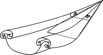
value. Fig.3.5(a) shows an example where separation occurs along the side and trailing edges of a tapered wing but where the flow remains attached over the leading edges. Since we have already seen in connection with Fig. 2.5 that such an attached flow is difficult to achieve when the angle of sweep of the leading edge is high, we may design for a separated flow instead by making the leading edges aerodynamically sharp. The resulting flow is then typically like that sketched in Fig.3.5(b). Carrying the abstraction one step further, we arrive at a conical flow with two large rolled-up vortex cores growing above the wing. On a complete wing, as shown in Fig. 3.6, the flow may be essentially conical over the front part. This flow fulfils the engineering requirements we have; it may be regarded as the archetype of the second basic type of flow. The corresponding types of aircraft will be discussed in Chapters 6 and 7.
This type of flow with coiled leading-edge vortex sheets over slender wings can exist at subsonic as well as supersonic flight speeds, and so a slender aircraft can be designed to have the same type of flow throughout its flight range. At supersonic speeds, the leading-edge vortex sheets may be relatively weak, and a slender wing may be so designed that the sheets vanish at the cruise condition and the attachment line lies along the leading edge. One
|
a TAPERED WING WITH TIP VORTEX SHEETS |
|
b SLENDER DELTA WING WITH SPIRAL LEADING-EDGE VORTEX SHEETS |
Fig. 3.5 Wings with flow separation from side edges
|
Fig. 3.6 Model of the flow past a lifting slender wing. After R L Maltby |
condition for this type of flow to exist at supersonic speeds is that the leading edges should lie well within the Mach cone from the apex, that is, the leading edges should be nominally subsonic in that the component Mach number normal to the leading edge remains subsonic. If the leading edges were to approach the Mach cone, the flow would change from the design type sketched in Fig. 2.8(c) to that sketched in Fig. 2.13 (albeit with sharp leading edges).
In principle, the lift and drag forces acting on these slender wings can be determined from the general relations (3.7) and (3.8). We may also assume that the perturbations caused by the wing are small. A theory based on this assumption will be described in Section 4.9 and Chapter 6 and used to show that these wings also operate best at supersonic speeds if their leading edges
lie well within the Mach cone from the apex so that the practical design conditions are indeed consistent with the type of flow that has been assumed.
Aircraft may be designed to have either of the two basic types of flow we have identified so far for flight at subsonic speeds and also at supersonic speeds. But it will become increasingly difficult to keep the perturbations small, as is required in these flows, as the Mach number of flight is increased. Therefore, we must look for yet another type of flow which incorporates shockwaves and expansions.


