SUDDEN ACCELERATION OF A FLAT PLATE
One of the simplest and yet the most basic examples of unsteady aerodynamics is the sudden acceleration motion of an airfoil.13 2 This example will be studied first by the simple “lumped vortex” method so that the most basic differences between this case and the steady flow case will be highlighted.
Consider the thin, uncambered airfoil shown in the upper part of Fig.
13.7
to be at rest at Г <0. Then at t – 0 the airfoil is suddenly accelerated to a constant velocity (/„. The boundary condition for />0 and for small a, according to Eq. (13.30) is
Now let us represent the airfoil by a lumped vortex element. By doing so, a single vortex solution is selected instead of the more general form of Eq. (13.15) that includes doublets and sources. Also, by placing the vortex at the quarter chord, the Kutta condition is assumed to be satisfied for this case.
JV4 Af2
Э і 9 і 9 і *•) 1 ‘« = 4Аг
|
f і*-, ^ І Э І = 2Л’ |
![]()
 |
к
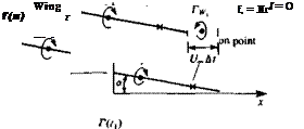
FIGURE 13.7
Development of the wake after the plunging motion of a flat plate modeled by a single lumped vortex element.
At this point also a wake model has to be established and here a discrete vortex wake is selected (Fig. 13.7). Now at a time = At, the airfoil already has traveled a distance t/„ At and its circulation is Г(г,). Recalling Kelvin’s theorem (Eq. (13.6)), the airfoil-bound circulation has to be canceled with a starting vortex (Fig. 13.7, at tx = At). The concentrated wake vortex has to be placed along the path traveled by the trailing edge, during this interval, so that the discretization effect will be minimal. At this point the middle of the interval is selected and the effect of this choice can be demonstrated later.
The zero normal flow boundary condition is satisfied at the collocation point at the plate’s three-quarter chord point (as shown by the x in Fig. 13.7) where the downwash induced by the bound vortex is
and the downwash induced by the first wake vortex is approximated by
|
|
|
assuming a« 1. The boundary condition дФ/dz = – U^a for the first time step then becomes
|
This equation can be rewritten in the form
wb + % + U^a – 0
which indicates that the sum of the velocity induced by the airfoil wb, the wake ww and the free stream must be zero. An additional equation is obtained by using the Kelvin condition
—=^0 + ^ = 0
Note that Г is considered positive for right-hand rotation, and in Fig. 13.7 for illustration purposes and with the knowledge of the solution, the wake vortex is drawn in the negative direction.
The above set of two equations with two unknowns is solved for Г(гі) and IVj. Now, after the second time step the airfoil has moved to a new location, as shown in the figure (for t2 = 2At). It was assumed in Section 2.9 that for high Reynolds number flows vortex decay is negligible (and zero for irrotational flow) and therefore the strength of rW| will not change with time. It is possible to calculate the induced velocity at the wake vortex and then move it along the local streamline, but for simplicity it is assumed here that its location remains unchanged (in the inertial frame).
At t = 2 At, the two equations describing the “no-flow-across-the-airfoil” boundary condition and the Kelvin condition are:
|
|
T(f2) + rv2 + rWl – 0
This set is solved for Г(г2) and TW2 while TWl is known from the previous calculation at t = tx.
At t = 3 At, the two equations can be written in a similar manner:
|
|
Г(*з) + Гіу3 + г W2 + г Wl = о
Again this set is solved for T(f3) and Г*,,, while TW2 and TW| are known from the previous calculations.
In this simplified analysis it was assumed that a is very small and the distance to the collocation points can be approximated by
and that the induced velocity is normal to the surface. Of course, numerically this error can easily be corrected.
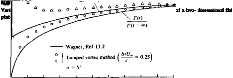
The results of this computation for Г(г) (shown by the circles), along with a more accurate solution, are presented in Fig. 13.8. The circulation at t = 0 is zero since the airfoil is still at rest. At t > 0 the circulation increases but is far less than the steady-state value due to the downwash of the starting vortex. In this two-dimensional case the increase of the circulation is slow and this transient growth extends to infinity.
 |
To compute the lift, the small-disturbance approximation (V,* » |V*^|) is applied to the unsteady Bernoulli equation (Eq. (13.23)):
and the pressure difference between the airfoil’s upper and lower surface is
![]() )= pU^y(x) + pjJ y(x)dx (13.35)
)= pU^y(x) + pjJ y(x)dx (13.35)
Here we used the results of Eq. (3.147) for a planar vortex distribution where the upper surface induced velocity is УФ = (y/2, 0, 0).
For the lumped vortex method there is only one airfoil vortex and therefore the lift L’ per unit span is
 (13.36)
Results of this simple model (triangular symbols) along with the exact solution of Wagner13 2 are presented in Fig. 13.8. The lift at / = 0+ is exactly half of the steady-state lift, but this lift is not due to the airfoil circulation (circulatory force) but due to the acceleration portion of the lift that is a result of the change in the upwash (ЭФ/dt). The magnitude of this force due to fluid acceleration becomes smaller with the reduced influence of the starting vortex. At t = 0 when the airfoil was suddenly accelerated from rest the lift was infinite, due to this acceleration term as shown in Fig. 13.8.
 |
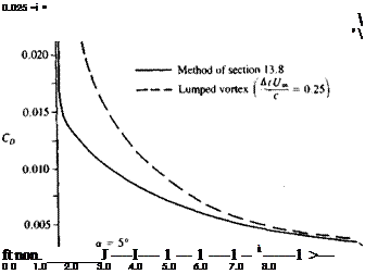
It is interesting to point out that for a two-dimensional airfoil there is a drag force during the transient. This drag force will have two components, due
9.0 v °°
l/=r
FIGURE 13.9
Varation of drag after the initiation of a sudden forward motion of a two-dimensional flat plate.
|
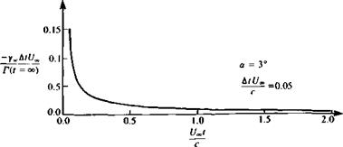
FIGURE 13.10 Wake circulation distribution behind the flat plate which was suddenly set into motion. |
to the two terms of the lift in Eq. (13.36). The first is due to the wake-induced downwash, which rotates the circulatory lift term by an induced angle ww/(J„. The second is due to the fluid acceleration ЭФ/dt which acts normal to the flat plate and its contribution to the drag is a times the second lift term in Eq.
(13.36) . Consequently the drag force is
D = p[wv(*, f)T(r) + T(r)caj (13.37)
Here the first term is due to the wake-induced downwash ww(x, t), which in the lumped vortex case is evaluated at the three-quarter chord point. The second term is due to the fluid acceleration and its center of pressure is a function of the change in the momentary chordwise downwash, which is closer to the aft section of the airfoil and varies with time. Calculated drag coefficients with this method and with a more accurate method131 are presented in Fig. 13.9.
While examining the wake vorticity as presented in Fig. 13.10, it can be observed that the first vortices are the strongest and that all vortices have counterclockwise (negative) values. Consequently, when the wake is allowed to rollup, due to the velocity field induced by the wake and the airfoil, the shape shown in Fig. 13.11 will be obtained.
|
a = 3°
FIGURE 13.11 Wake rollup behind a two-dimensional flat plate which was suddenly set into motion. |
A simple computer program based on the formulation of this section is presented in Appendix D, Program No. 13.


