Types of Rotors
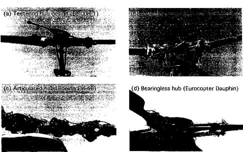
There are basically four types of helicopter rotor hubs in use. These are the teetering design, the articulated design, the hingeless design and the bearingless design. A teetering rotor has two blades that are hinged at the rotational axis (i. e., on the shaft) and uses no independent flap or lead-lag hinges. The well-known Bell (Young) design shown in Fig. 4.2(a) is an example of a teetering rotor design. The blades are connected together, so that as one blade flaps up the other flaps down like a seesaw or teeter board. A separate pitch or feathering bearing on each blade allows for cyclic and collective pitch capability. A stabilizer bar may be included, which acts like a gyroscope maintaining its orientation in space and introduces a flapping-blade cyclic pitch feedback, which gives the helicopter
|
Figure 4.2 Various types of rotor hubs, (a) Bell teetering hub design. Notice the bob weights attached to the stabilizer bar. (b) An articulated hub, in this case with coincident flapping and lag hinges, (c) An articulated hub, with the lag hinge outboard of both the flap and feathering bearing, (d) A bearingless hub, where the mechanical hinges are replaced by flexures. |
increased flight stability. The teetering design has the advantage of being mechanically simple with a low parts count and it is easy to maintain. One disadvantage of the design is that it can have a relatively high parasitic drag in forward flight, in part because of the stabilizer bar. On later teetering rotor designs, the stabilizer bar has been removed.
A variation of the teetering design is the underslung teetering hub, an example being used on the Bell-Huey series of helicopters. Here, the blades are given a precone angle so that a downward (negative) bending component resulting from the centrifugal forces produced by blade rotation eliminates the upward (positive) bending moment at the hub resulting from the aerodynamic loads. However, any precone displacement will move the center of gravity of the rotor system above the axis of the teetering hinge, and this can introduce an undesirable coupling into the rotor system through Coriolis effects. To prevent this, the rotor is underslung below the teetering hinge to minimize the center of gravity movement relative to the shaft. A problem, however, that has arisen with underslung teetering rotor designs is mast bumping, which occurs when the rotor is lightly loaded (such as in a push-over maneuver) and excessive blade flapping causes the blade hub to contact the rotor shaft. While snubbers are used to help prevent this, repetition of the problem can result in damage to the rotor shaft. Another variation of the teetering design, called the gimbaled hub, is used on tilt-rotor aircraft such as the V-22 Osprey, where the three blades and the hub are attached to the rotor shaft by means of a gimbal or universal joint.
A large number of helicopters use conventional or fully articulated rotor hubs. Here, mechanical flap and lead-lag hinges are provided on each blade along with a feathering bearing. Different helicopters use various sequences of hinges and bearings, and this affects the dynamics of the rotor system. Many Sikorsky helicopters use coincident flap and lead-lag hinges, with the feathering bearing located further outboard [see Fig. 4.2(b)].
The Boeing CH-46 and CH-47 helicopters use a lead-lag hinge outboard of the feathering bearing [see Fig. 4.2(c)]. In both cases, because of the relatively low drag and aerodynamic damping in the lead-lag plane, mechanical dampers are fitted at the lag hinges. Needless to say, the articulated rotor design is mechanically complicated with many component parts and is relatively expensive to maintain. It is also heavy and produces relatively high drag in forward flight. Nevertheless, the fully articulated design is the classic approach to providing blade articulation on a helicopter and in practice it has proven mechanically reliable but with relatively high maintenance costs because of the large number of parts.
A hingeless rotor design eliminates the flap and lead-lag hinges by using a flexure to accommodate blade motion. A feathering bearing is still used to allow for pitch changes on each blade. The advantage of a hingeless design is that it is mechanically simple. However, because blade articulation is achieved by the elastic flexing of a structural beam, the design of such rotors is rather complicated. In addition, because it is not possible to completely isolate the flapping motion from the lead-lag motion there is usually significant flap-lag coupling to contend with. Major advantages of the hingeless hub design include mechanical simplicity with a low parts count and low aerodynamic drag. In addition, the relatively stiff hub design gives the helicopter a powerful response to control inputs and increased maneuvering capability.
Bearingless hub designs are a relatively new innovation. In addition to eliminating the mechanical flap and lead-lag hinges, the bearingless hub also eliminates the feathering bearing. All three degrees of motion are obtained by bending, flexing, and twisting of the hub structure. Needless to say, obtaining the required stiffnesses is only possible by means of new fatigue-resistant composite materials such as glass, carbon, and Kevlar, which can be arranged so that load paths, stiffnesses, and couplings can all be controlled. Designing a bearingless hub is difficult and requires a detailed (i. e., finite-element based) structural dynamic analysis. While retaining all the advantages of a hingeless design, bearingless hubs can be particularly susceptible to aeromechanical instabilities as a result of low in-plane damping of the lead-lag blade motion.


