Coupled Flap-Lag Motion
It will be apparent from the foregoing that, in practice, the blade flapping and lead-lag motion are coupled. Now consider the analysis of the problem where the blade simultaneously undergoes two types of motion with both flapping and lead-lagging about their respective hinges. This type of model is a good representation of a blade with a high torsional stiffness. For simplicity, it will be assumed that the flapping and lead-lagging hinges are coincident. In this case, note that the flapping and lead-lag motions are coupled as
a result of Coriolis and aerodynamic forces. Coriolis effects introduce an important coupling between blade flapping or out-of-plane motion and lead-lag or in-plane motion. The Coriolis effect is an additional inertial force, first described by Gustave-Gaspard Coriolis in 1835. Coriolis showed that in a rotating frame of reference, an inertial force must be included into the general equations of motion. On a rotor, Coriolis forces will appear whenever there is a radial lengthening or shortening of the blade about the rotational axis, which will be a result of blade flapping or bending. Coriolis effects produce forces in the plane of rotation of the rotor.
A more complete description of the various forces acting on the rotor can now be obtained. For the flapping motion, the forces acting on the blade element are as follows:
 |
where the lagging frequency can be found from

and the coning angle now becomes
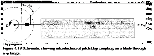
which relative to the case without pitch-flap coupling is reduced for a given collective pitch. On tail rotors, the <$3 angle is close to 45°, which makes the effect significant. Two examples of tail rotors sporting a 83 hinge are shown in Fig. 4.20.
4.13.1 Teetering Rotor
The teetering (or seesaw) rotor design has already been mentioned; the two interconnected blades form a single structure and have a flapping hinge located on the shaft axis. The teetering design uses no independent flap or lead-lag hinges. An example is shown in Fig. 4.20(a) and is illustrated schematically in Fig. 4.21. The blades may have a built-in precone angle, /Sp, which reduces lift-induced steady bending loads. A 83 angle may be included, which as previously mentioned, reduces cyclic flapping and Coriolis effects. A separate pitch or feathering bearing on each blade allows for cyclic and collective pitch capability.
The dynamic flapping motion of the teetering rotor is obtained by considering simultaneously the equilibrium of forces on both blades. Consider the flapping moments about the
Rotational
 1 Teeter hinge
—sc
Figure 4.21 A teetering rotor design has two interconnected blades that behave as a single rotating system.
teeter hinge. Each blade has a contribution to the moment, which is equivalent to twice the moment produced by any one blade. This means that
and for the other blade, which is located at + л, the flapping motion is
OO
02(VO = – 0i = 0o + lA*c cos n№ + + 0И* sinn(f + я)]. (4.94)
n—1
This latter equation may be written as
OO
= 2PP – fa =0o + ^(-1)" (0nc cos nxjs + fins sin nrjr). (4.95)
n= і
Substituting Eq. 4.93 into Eq. 4.95 and equating trigonometric coefficients gives
OO
02(VO = 0p + (Pnc cos nФ + 0»J sinnf). (4.96)
n odd
This means that for the teetering rotor the coning angle is equal to the precone angle fip and also that only the odd harmonics of flapping are present; the even harmonics cancel and the effects are reacted as structural stresses internal to the rotor hub. Because the harmonics of n > 3 are small they may be neglected. Only the first harmonics of flapping remain, which control the orientation of the rotor tip path plane. This means that all the solutions obtained for the articulated rotor also apply to the teetering rotor, but only if they are referred to the
/4*. Mlm
олій ui no l^aui&iuig ui iyr. r.


