Dynamics of a Lagging Blade with a Hinge Offset
The blade is assumed to be rigid and undergoes a simple lagging in the plane of rotation about a hinge located at a distance eR from the rotational axis. The various forces acting on the blade are now:
1. The inertia force mx dy = m(y — eR)£ dy, acting at a distance (y — eR) about the lag hinge.
2. The centrifugal force mO,2y dy acting at a distance eRx/y from the rotational axis, where x = (y — eR)/i;.
3. The aerodynamic drag force D dy acting at a distance (y — eR) from the hinge axis.
Taking moments about the lag hinge gives
pR pR gft pR
I m(y — eR)2£ dy + I m£22y(y — eR)—£ dy — I D(y — eR)dy = 0. JeR JeR У JeR
(А 11Л
The mass moment of inertia 1^ about the lag hinge is
![]() Therefore, the equation of motion for lagging about the lead-lag hinge can be written as
Therefore, the equation of motion for lagging about the lead-lag hinge can be written as
h(i + ^) = ^[RDiy-eR)dy,
where is the nondimensional lag frequency in terms of the rotational speed, as determined from
which is shown graphically in Fig. 4.17. Because the centrifugal restoring moment about the lag hinge is much smaller than in flapping, the corresponding uncoupled natural frequency of the lag motion is much smaller. For articulated rotors, the uncoupled rotating lag frequency varies from about 0.2 to 0.3Q (see also Question 4.9). For hingeless designs, the value of is much higher, typically from 0.6 to 0.8£2.
Notice that the lag motion of the blade is lightly damped. Besides the fact that the lead – lag displacements about the hinge are small, they only produce aerodynamic forces through changes in velocity and dynamic pressure normal to the leading edge of the blade. This has a much smaller effect than the aerodynamic forces produced by changes in AoA induced
hv ЫяНр. Яяппіпа motion Alert thp Нгяа fnrrpc ar*tina rtn the* ЫяНр. с ягй almnct twn rtrH^rc ~**«rr***& 4,44 W4V ~**~*~~ V4A4A1VWV fcTTV V4V4WU
of magnitude less than the lift forces. Therefore, because of the low inherent damping it is
found that the blade lag motion is very susceptible to driving various types of aeroelastic
and aeromechanical instabilities on the rotor.
One important example of an aeromechanical instability associated with blade lag motion
is ground resonance, where the blade lag motion and the in-plane motion of the fuselage
become coupled to produce a catastrophic aeromechanical instability. Ground resonance
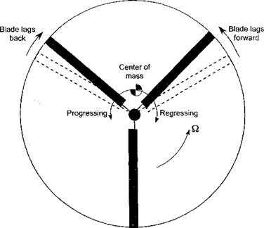
is associated with the out of pattern in-plane motion of the blades (see Fig. 4.18) and a
coupling with the dynamics of the undercarriage and wheels of the helicopter when on the
ground. When the motion of the center of gravity is in the same direction of rotor rotation it is
|
Figure 4.18 Ground resonance is a potentially catastrophic aeromechanical instability of the rotor resulting from an out-of-pattem in-plane lead-lag motion of the blades and its coupling with airframe motion on its landing gear. |
called the progressive lag mode, and when in the opposite direction it is called the regressive lag mode. The problem of ground resonance occurs when the frequency of the regressive lag mode corresponds to an airframe frequency. This causes the net center of gravity of the rotor system to spiral outward away from the rotor hub, initially resulting in a severe shaking of the machine and quickly leading to a catastrophic resonance. “Sympathetic” pilot inputs through the flight controls can provide the initial excitation to the rotor system, although taxiing the machine over rough ground can also be a culprit. A related problem is called air resonance, which occurs in flight when the regressive lag mode couples with the fuselage roll and pitch motions, and this too can also be disastrous. This is the reason why most helicopter rotors have mechanical lag dampers, which provide artificial damping to suppress the occurrence of aeromechanical phenomena. If the lag frequency is larger than the rotational frequency (i. e., for a stiff in-plane rotor blade), then there is no possibility of ground or air resonance instability. Coleman & Feingold (1958) developed the first mathematical theory to predict and cure the problem of ground resonance, although even here several aerodynamic approximations are involved. A good summary of the theory of ground resonance is also given by Bramwell (1976) and Johnson (1980).


