Examples of the Art of Approximation
A significant breakthrough in applying the equations of fluid dynamics in an approximate way to represent the solution to an important aerodynamics problem is due to Ludwig Prandtl. His genius in realizing that many complex flow problems of practical interest may be decomposed into (1) an inviscid irrotational part, potential flow, and (2) a viscosity-dominated part, boundary layer flow, revolutionized aeronautical thinking in the early years of the twentieth century. The equations that describe the component parts are vastly simplified and can be solved separately. The two separate solutions are “matched” so that all of the boundary conditions are accommodated. This yields a remarkably satisfactory solution for many practical problems in aerodynamics. This decomposition into simpler parts, along with the subsequent synthesis into a complete solution, is the basis of a powerful approach to many engineering problems. It also is the foundation of an analytical technique called the perturbation method that has been used to produce many of the standard solutions used by all practicing engineers. Various versions of this approach are used to linearize the sometimes nonlinear governing equations in a given aerodynamics problem.
We examine many such problems and their solutions in this book. The perturbation approach can be used when a key parameter occurring in the formulation is either very small or very large. A famous example is the solution for compressible flow over a slender wing or body: the small-disturbance theory. In that situation, the size of the object measured perpendicular to the flow (e. g., h) can be considered small compared to the length, L, along the direction of the flow. Then, the ratio of these two physical lengths results in a small perturbation parameter—call it e:
h
e = —,
L
which can be used to greatly simplify the governing equations. For example, if a particular term in one equation is proportional to the square (e2) or cube (e3) of this small parameter, such a term often can be dropped. This is because it is implied that it is very small compared to terms that either do not involve the small parameter directly or contain it only to the first power. The equations remaining when the presumed small parts are discarded lead to what is called the linearized formulation of the problem.
If analytical solutions of the defining partial-differential equations are sought, general simplifications must be made, even after the problem has been decomposed. They may involve dropping irrelevant terms and/or neglecting certain terms as negligible compared to other terms in an equation in a particular physical situ – ation—thus, the importance of understanding the physical basis for the equation and the physical reason for the appearance of each term. Only then can a reasonable approximation be carried out that results in an approximate theory yielding satisfactorily accurate results.
3.7 Summary
Because there are many special forms of the three equations (i. e., continuity, momentum, and energy) that govern an aerodynamic flow, they are tabulated in concise form throughout the chapter. The tables are arranged to enable the student to readily find the form needed in a particular situation and to check the limitations that apply and the degree of approximation being made.
PROBLEMS
3.1 Two streams of water (p = constant = 2 slug/ft3) enter a duct as shown here. The flow is parallel to the duct centerline. Stream A enters with a uniform velocity of 5 ft/s and Stream B enters with a velocity of 25 ft/s. Both streams have a constant area of 1 ft2 and the duct has a constant area of 2 ft2. The two flows mix thoroughly, resulting in a uniform velocity at Station 2. Assume a steady flow. What is the velocity at Station 2?
_____
©
Problem 3.1
3.2
 |
An incompressible j et flows into and out of a bent pipe at atmospheric pressure. The pipe is mounted on a frictionless roller and is restrained by a spring. Two pipe bend angles are available, as shown. Determine which configuration causes the smallest deflection of the spring. Assume a steady, inviscid flow.
3.3
 |
Rework Example Problem 3.5 using the specified control volume and absolute pressure. Recognize that when the control surface cuts through the support strut, there is a force imposed on the control surface at that point.
3.4 A long cylindrical body of revolution with a cross-sectional area of 2 ft2 is installed in a constant-area duct of 5 ft2, as shown. The flow is steady and incompressible. Assume that the viscous effects are negligible and the flow is one-dimensional. Find the pressure force acting on the nose of the body in the streamwise direction. Assume p = 0.2 slugs/ft3. Show the control volume used in the calculation and give the units of the answer.
 |
 |
© ©
3.5
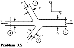 |
Two jets of water with the same velocity impinge on one another, forming two other water jets, as shown. Assume a steady, inviscid flow of unit depth into the page. Also assume that all of the jets have a uniform flow. Calculate the jet width t2. Show the control surface used in the calculation and give the units of the answer.
3.6
 |
|
A free-jet flow passes through a fixed cascade of turbine blades in a test stand at ambient pressure. Assume that the jet flow is inviscid (i. e., no losses) and steady and that the cascade turns the jet flow through a 45° angle. Calculate the lift and drag on the cascade. The flow may be taken as two-dimensional. Show the control volume used in the calculation and give the units for the answer.
Problem 3.6
3.7
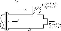 |
A liquid (p = 64.4 lbm/ft3) flows through a vent pipe and discharges to the atmosphere through two jets, as shown (p2 = p3 = ambient pressure). At Station 1, the vent pipe is bolted to the supply pipe by means of a flange. The static pressure at Station 1 is 12 psi above ambient pressure. Assume that the flow is steady and incompressible; ignore viscous and gravity effects. Show the control volume used in the calculation and give the units for the answer. Calculate the %-component of force on the coupling. Are the bolts in tension or compression?
3.8 A pipe receives a steady flow of liquid (p = 2 slug/ft3) through Station 1 and discharges into two other pipes at Stations 2 and 3. The volume flow rate through Station 2 is measured as 40 ft3/s. The pipe is restrained by a support, as shown. The couplings cannot support any load. Assume an inviscid one-dimensional incompressible flow. Ignore gravity effects and the weight of the pipe. Show the control volume used in the calculation and give the units for the answers. Find: (a) exit area A3
(b) у-component of force on the support: magnitude direction (up, down).
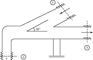 Pamb = 2,000 Psfa Pi = 3,000 psfa p2 = 2,100 psfa p3 = 1,000 psfa
A1 = 4 ft2
A2 = 0.8 ft2 V1 = 40 ft/s V3 = 60 ft/s
Problem 3.8
3.9 An air compressor takes in air at standard conditions (use 14.7 psia and 70°F) at a negligible velocity. The air is discharged at 115 psia and 125°F with a density of 0.5 lbm/ft3. The mass flow rate out of the 0.5 ft2 discharge pipe is 12 lbm/s. If the compressor input horsepower is 800, find the magnitude and direction (in words) of the heat transfer to/from the compressor in units of BTU/s. Assume a steady flow. Draw a control surface for the calculation.
3.10 A steady flow of a gas passes into and out of a certain device. At the inlet, Station 1, T = 140°F and V1 = 20 ft/s. At the outlet, Station 2, T2 = 600°R and V2 = 30 ft/s. In passing through the device, 2 BTU/s of heat is extracted from the flowing medium and 4 HP of machine work is done on the flowing medium by an outside source. Calculate the mass flow rate through the device (slug/s). Ignore gravity effects and assume an inviscid flow. Draw a control surface for the calculation.
3.11 A steady flow of air at 5 slug/s passes through a certain device, entering at 100 ft/s and exiting at 200 ft/s. The entrance and exit static enthalpy of the air is the same, and 10 HP is supplied to the device. What amount of heat (BTU/s) is being added to (or subtracted from) the device? State the heat flux and direction. Assume an inviscid flow and ignore gravity effects. Draw a control surface for the calculation.
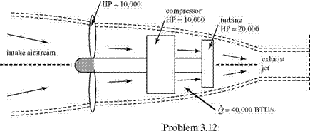
3.12 Consider the turboprop engine shown here. The intake and exhaust airflow rates are 100 lbm/s and the stagnation enthalpy of the entering air is 120 BTU/ lbm. The turbine, compressor, and propeller HP are 20,000, 10,000, and 10,000,
 |
|
respectively. The turbine drives the compressor and the propeller. Assume that the propeller does no work on the intake air; however, it does work on the air outside of the engine. Compute the jet stagnation enthalpy, hoj, assuming a uniform and steady flow. Use the suggested control volume and give the units for the answer. Then, work the problem again by doing it in two steps: the first step based on a control surface extending from upstream of the propeller to just downstream of the compressor, and the second step using a control surface extending from just downstream of the compressor to well downstream in the jet exhaust.
3.13 The velocity components u and v in a two-dimensional flow field are given by:
u = 4yt ft/s, v = 4xt ft/s,
where t is time. What is the time rate of change of the velocity vector V (i. e., the acceleration vector) for a fluid particle at x = 1 ft and y = 1 ft at time t = 1 second?
3.14 Consider a two-dimensional, incompressible, inviscid flow field given by:
V = (3x + 4t2 )i + (2x – 3y)j
a. What is the pressure gradient in the x-direction at a point (x = 2, y = 3) at t = 1/2 second? Assume the density of the flow to be 0.2 slug/ft3.
b. What is the convective acceleration of a particle in this flow field in the y-direction at (x, y,t) = (3,2,1)?
3.15
 |
The two-dimensional channel shown here has a linear variation of area between Stations 1 and 2 and has a steady volume flow rate of 20 ft3/s per unit width of channel. What is the convective acceleration of a fluid particle at x = 2 ft? Give the units for the answer.
3.16 Follow the same method used to derive Eq. 3.74 to determine the three-dimensional form of the differential-momentum equation.
3.17 Using the vector form of the differential-momentum equation, deduce the three scalar components of the momentum equation in cylindrical coordinates (see Fig. 3.4).
3.18 Use the differential-element method to find the momentum equation in threedimensional polar coordinates (see Fig. 3.4). Reduce to the two-dimensional form (i. e., no dependence on the z-coordinate) and compare to the results for Problem 3.17.
3.19 Use the differential-element method to find the momentum equation in threedimensional spherical coordinates. Compare the results to the appropriate tables in the appendix.
REFERENCES AND SUGGESTED READING
Johnson, Richard W., The Handbook of Fluid Dynamics, CRC Press, LLC, 1998.
Kuethe, A. M., and Schetzer, J. D., Foundations of Aerodynamics, 2nd ed., John Wiley & Sons, New York, 1961.
Schlichting, Hermann, Boundary Layer Theory, 7th ed., McGraw-Hill Book Company, New York, 1979.
Serrin J., “Mathematical Principles of Classic Fluid Dynamics,” Flugge S. (ed.), Handbuch der Physik VIII/1, Springer-Verlag, Berlin, Heidelberg, New York, pp. 125-263, 1959.
Wilcox, David C., Basic Fluid Mechanics, Third Edition, DCW Industries, Inc., 2007.


