Results
The calculated unsteady aerodynamics agree very well with the unsteady Laser-2-Focus measurement data from the rig test (the time-averaged absolute velocity is presented in Fig. 3, the amplitude of the 1st harmonic of the absolute velocity in Fig. 4). As the (optical) vibration control system of the rig test monitored only low frequency excitations during running up, and no strain gauge measurements were taken, the comparison with the unsteady aerodynamic measurement data is the only possible comparison with experimental data here. The following aeroelastic investigation is based on these qualified unsteady aerodynamics, but of a numerical nature only.
0.0003

![]()
![]()
 0.0002
0.0001
-*0.0000 СГ
-0.0001 -0.0002
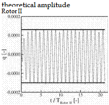
Figure 5. Temporal development of blade displacements in their eigenmodes
The vibration amplitudes obtained from the time development of the fully coupled aeroelastic simulation are the same as those predicted by the linear approach (Fig. 5). The absolute vibration amplitudes are moderate: The maximum displacements at the tip trailing edges are 36% of the trailing edge thickness for the first rotor, and 20% for the second rotor. Only small amplitudes would have been expected here for two reasons: 1. The excitation of higher order mode shapes is in general small as a complex mode shape is unlikely to by severely excited (the exciting aerodynamic pattern has to fit the mode shape for which the chances are low for complex mode shapes). 2. The investigated configuration is an existing rig stage that does not feature any severe forced response problem. Severe problems would have been avoided already in the design phase of the rig. The very good agreement between the coupled simulation and the linear solution is astonishing here as the coupled calculation computes the blade displacements of the first and the second rotor in one common simulation. So the coupled simulation allows each vibrating blade to change the aerodynamics in the stage, and therefore to change the aerodynamic disturbance (or “gust”) on the other blade. The linear model on the other hand computes the displacements separately, and it suppresses any infhence of the vibrating blade to the other blade. The linear model computes the solution to the forced response problem with one stiff (exciting) blade and one elastic (excited) blade.
The comparison of the coupled aeroelastic simulation with the linear solution is extended to the unsteady fbw fields in the blade passages. In a postprocessing step, the unsteady aerodynamic solutions from the decoupled calculations of the aerodynamic damping (each rotor alone) and the aerodynamic forcing (stage with stiff blades) are combined to a “superposed” aerodynamic
|
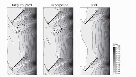
Figure 6. Amplitude of pressure flictuations in the passage of the 1st rotor near tip |
solution. This is an aerodynamic solution taking into account the vibrating blades by the use of the principle of superposition. "Superposed” and ‘fully coupled” solutions show identical unsteady aerodynamics inside the blade passages. Figure 6 shows the amplitude of perturbation pressure in the passage of the first rotor near the tip. The source of the pressure amplitudes visible in the exit plane of the rotor, and decaying when running upstream, is the not shown downstream second rotor that excites the first one. The two solutions taking into account the blade vibration (the “coupled” and ‘Superposed” solution) differ (Fig. 6: ‘k’) from the aerodynamic solution with ‘stiff” blades that neglects the blade vibration. The example shows the first rotor’s tip section, but the same result was found for the full span as well as the second rotor. The agreement between “coupled” and “superposed” solutions, and disparity with the ‘stiff” solution, for the amplitudes, was also evident for the phases. Figure 7 presents the unsteady pressure distributions on the blade surfaces, here exemplarily for the second rotor. The agreement between the “superposed” and ‘‘fully coupled” solution is very good even in quantitative terms. The results from the ‘stiff” calculation deviate as the blade vibration is not incorporated there at all.
Both the blade row interaction and the blade vibration generate unsteady pressure fbctuations on the blade. If the blade row interaction and the blade vibration are computed separately, the local aerodynamic forcing as well as the local aerodynamic damping can be computed by a projection of the blade surface pressure amplitudes onto the blade eigenmodes (often referred to as local aerodynamic work coefficient). This was applied to the separate computations
|
Figure 7. Amplitude of blade surface pressure of the 2nd rotor |
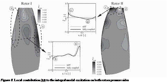
of forcing and damping and yielded in a straight-forward manner the excitation mechanisms due to the more or less matching of the three-dimensional pattern of the pressure fhctuations on the one hand and the mode shape of the blade vibration on the other hand. The integral of this local contribution over the blade surface yields the integral modal forcing and damping respectively. For the fully coupled solution at resonance, the integral modal forcing is expected to be zero. That is the damping counterbalances the forcing. An analysis of the frequency spectrum of the integral modal force taken from the coupled simulation showed as expected a vanishing contribution of the harmonic at excitation frequency. Figure 8 shows the local contribution to the integral excitation from the “coupled” simulation for the pressure sides of both rotors. Parts of the blade surface contribute to the excitation (positive values), others to damping (negative values). The integral of the local forcing contribution over the blade surface is zero as already mentioned. The diagrams in the center compare the local excitation contribution to the result computed with stiff blades, which features of course a significant and positive integral modal forcing when integrated over the blade surface. The comparison shows for the “coupled” simulation as compared with the ‘stiff” solution, a reduction of the excitation in exciting blade surface areas (‘h” and “c”), as well as at the same time an increase of damping in the damping areas of the blade surfaces (“b” and “d”). This is in full agreement with the anticipation based on a point of view that the pressure fluctuation generated by the vibrating blades are looked upon as additional fluctuations to the already present fluctuations from blade row interaction. The additional fluctuations from the blade vibration then change
 |
the sum pressure fhctuation pattern in such a manner that the integral over the surface becomes zero, so neither exciting nor damping. This corresponds to a blade vibration with a constant amplitude.
1. Conclusions
The numerical investigation shows a full agreement of the fully coupled solution with the solution obtained from the superposition of the decoupled simulations: This does not only hold for the vibration amplitudes, but even for the unsteady pressure distributions qualitatively as well as quantitatively. For the case under consideration, this confirms the validity of the superposition principle for the aerodynamics in cases of forced response.
The very good agreement between the coupled and the linear solution can be also looked upon from another point of view: For the present case, apparently the computed aerodynamic damping is not significantly inflienced by the blade row interaction (the theoretical inflience of blade row interference on flitter and forced response is described in Buffum, 1995).
The proven validity of the principle of superposition supports the forced response analysis currently applied within industry. There remain two advantages for the coupled analysis over the linear approach: 1. Only one coupled simulation is required for the full analysis of the system. The linear approach requires an increasing number of separate evaluations of the aerodynamic damping for complex configurations featuring multiple eigenmodes and frequencies (50 to 100 aerodynamic damping coefficients may be required
depending on the system’s complexity). 2. The decoupled analysis requires the rotor alone computations for the evaluation of the aerodynamic damping to have the same time-average operating point as the multi-stage configuration. This was the case for the current configuration. Multi-stage compressors and turbines with high loading and small axial gaps between blades can feature blade rows where the operating point in the multi-stage configuration cannot be reached in a single blade row computation. Reasons for this are steady or even unsteady multi-stage effects. As the required aerodynamic damping cannot not be evaluated correctly in these cases, the principle of superposition cannot be applied. But forced response investigations are very likely required in these cases with strong blade row interference. The coupled approach can still be applied without any restriction, and so remains the means to analyze the forced response in such a system.


