The Half-Plane Green’s Function
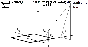
The emphasis is put here on the Green’s function of the space limited by a rigid half-plane with zero thickness, known as the half-plane Green’s function for the Helmholtz equation, because of its applications in aeroa – coustics, for instance in the analytical modeling of trailing-edge noise or high-lift device noise. Initially derived by Macdonald (1915) in spherical coordinates for a stationary medium, the expression is easily transposed in cylindrical coordinates for a source point x0 = (r0,d0,z0) and an observer at point x = (r, в, z), with the z axis along the edge and в being n along
 |
|
the half-plane and zero in its continuation (Fig. 13). It reads
![]() Mi
Mi
I K (i kR cosh £) d£,
— CO
where K is the modified Bessel function of the first kind and where the upper bounds are given by
R is the distance from the source to the observer R = [r2 + r2 + (z — z0)2 — 2rr0 cos(e — в0)]1/2, and the similar expression for the distance from the image point to the observer R holds with cos(e + в0). Equation (20) is the basis for deriving the radiated field of arbitrary source distributions accounting for the diffraction by the edge. The acoustic field of a point
dipole of force P is finally given by the scalar product P • VGu/2 and that of a quadrupole of strength Q by the double scalar product Q : VVg!,1/2).
 |
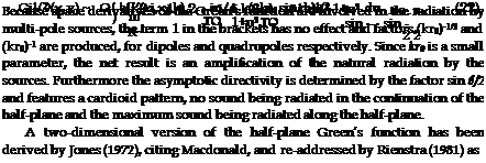
Most reported applications, such as the trailing-edge noise analysis proposed by Ffowcs Williams & Hall (1970), are based on the asymptotic form of the Green’s function for far-field observer and sources very close to the edge in terms of acoustic wavelengths. The asymptotic form reads
where the quantities r12 and ^1j2 are just deduced from the equivalent parameters in eq. (20) by putting z = z0 = 0.
A useful transformation can next be introduced to extend the preceding Green’s functions in a stationary medium to the case of a uniformly moving medium, provided that the fluid motion is along x1. The transposition formula reads
GM/2)(xbx3,k) = 1 Gi1/2)(Xbx3,K) e—iKM0 (Xi—Yi), (23)
where (X1,Y1) = (x1,y1)/e, K = k/в and where corrected angles accounting for flow convection are considered in original expressions. The transformation holds for two-dimensional and three-dimensional spaces, and
stretches the coordinate along the direction of the flow. In the two-dimensional case of a trailing edge, thus positive Mach number, a correction accounting for the Kutta condition has been proposed by Jones and re-addressed by Rienstra (1981). This condition has a noticeable effect at Mach numbers exceeding 0.5 and/or for sources located very close to the edge (see Roger & Moreau (2008)). It is ignored in the present discussion for conciseness.

 |
(a)
(b)
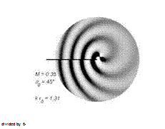
Exact two-dimensional radiation patterns obtained for the same point lateral quadrupole located at two different distances from a trailing edge are plotted in Fig. 14. The Mach number is 0.35, the source angle is 90 = 45° and no Kutta condition is applied. For the first plot (Fig. 14-a) the reduced distance to the edge is kr0 = 1.31 and the same spiral pattern as in free field is recognized. At same distance but at 90 = 135°, a shadow zone would be observed in the bottom part of the map because the half
plane would act as a screen. For the second plot (Fig. 14-b) at the reduced distance kr0 = 0.131 the asymptotic regime is reached and the radiation has the typical cardioid directivity imposed by the Green’s function, with wavefronts in phase opposition on both sides. The same would be found for other source angles at the same distance. This regime is accompanied by a strong amplification since the gray-scale has been artificially damped by a factor 6 in order to make both plots comparable. An even stronger amplification would be found imposing a Kutta condition. The asymptotic regime is typical of trailing-edge noise from attached turbulent boundary-layers. Indeed Lighthill’s interpretation followed by Ffowcs Williams & Hall (1970) involves quadrupoles remaining very close to the surface and the trailing edge in terms of acoustic wavelengths for all frequencies of interest. In contrast quadrupoles located farther away from the edge are amplification – free. From this fundamental result it is expected that attached turbulent flows over a trailing edge are much more efficient sound generators than small-scale vortical patterns developing, for instance, in the separated shear layers on stalled airfoils. According to Roger & Moreau (2008) the asymptotic regime is typically entered below kr0/fi ~ 0.4 for quadrupoles and below кг0/в ~ 0.2 for dipoles. As a result turbulence convected along a wall far from a singularity must be a poor source of sound. More precisely, classical results about the relationship between trailing-edge noise and wall-pressure statistics (see chapter 5) make the cut-off frequency of the sound spectrum expected around u5/U0 ~ 3 for loaded airfoils, where 5 is the boundary-layer thickness within which the quadrupole sources are distributed. A rough estimate of the condition for amplification associated with the asymptotic cardioid regime up to that frequency therefore reads 3(М0/в) r0/5 < 0.4. It appears that the condition is more easily satisfied at low speeds.
The asymptotic half-plane Green’s function also explains the directivity of the vortex-shedding sound emitted as a von Karman vortex street is formed in the near wake of a thin airfoil or plate with blunted trailing-edge. The roll-up of vortices features quadrupole sources that are scattered by the edge and the sound produced is again cardioid-like, with phase opposition on both sides of the plate. Because the shedding frequency is 0.2U0/h where h is the trailing-edge thickness and because the shorter expected edge-vortex distance is around h, now кг0/в ~ 0.4 n M0/fi is likely to be lower than 0.4 at low Mach numbers for the closest vortices. Despite the fact that they result from fundamentally different mechanisms, both trailing-edge noise and vortex-shedding noise have the same characteristic radiation properties imposed by the Green’s function. Oppositely a laminar separation bubble at leading edge is sometimes observed on thin airfoils, triggering a turbulent
reattached flow. Since the bubble free shear layer is initially laminar, it is a possible source of noise only if its first oscillations take place at a leading-edge distance below the threshold kro/в < 0.4, and if the favorable condition is fulfilled by frequencies effectively covered by the instabilities.


