Our heavyweight helicopter equal in the world does not have
In Rostov started production of the most load-lifting rotary-wing car The Russian holding «Helicopt[...]

Everything about aircrafts and helicopters. News and events in aviation worldwide. Civil, transportation, military helicopters and airplanes.

Everything about aircrafts and helicopters. News and events in aviation worldwide. Civil, transportation, military helicopters and airplanes.

Everything about aircrafts and helicopters. News and events in aviation worldwide. Civil, transportation, military helicopters and airplanes.

Everything about aircrafts and helicopters. News and events in aviation worldwide. Civil, transportation, military helicopters and airplanes.


Lift, drag, and lift-drag ratio Airplanes moving with constant velocity are subject to an aerodynamic force R (Fig. 1-5). The component of this force in direction of the incident flow is the drag D, the component normal to it the lift L.
Lift is produced almost exclusively by the wing, drag by all parts of the aircraft (wing, fuselage, empennage). Drag will be discussed in detail in the following chapters. It has several fluid mechanical causes: By friction (viscosity, turbulence) on the surfaces, friction drag is produced, which is composed of shear-stress drag and a friction-effected pressure drag. This kind of drag depends essentially on the aircraft geometry and determines mainly the drag at zero lift. It is called form drag or also profile drag. As a result of the generation of lift on the wing, a so-called induced drag is created in addition (eddy drag), which depends strongly on the aspect ratio (wing span/mean wing chord). An aircraft flying at supersonic velocity is subject to a so-called wave drag, in addition to the kinds of drag mentioned above. Wave drag is composed of a component for zero lift (form wave drag) and a component caused by the lift (lift-induced wave drag).
The inclination of the resultant R to the incident flow direction and consequently the ratio of lift to drag depend mainly on wing geometry and incident flow direction. A large value of this ratio L/D is desirable, because it can be considered to be an aerodynamic efficiency factor of the airplane. This efficiency factor has a distinct meaning in unpowered flight (glider flight) as can be seen from Fig. 1-5. For the straight, steady, gliding flight of an unpowered aircraft, the resultant R of the aerodynamic forces must be equal in magnitude to the weight W but with the sign reversed. The lift-drag ratio is given, therefore, after Fig. 1-5, by the relationship
where є is the angle between flight path and horizontal line.
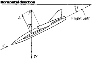 Figure 1-5 Demonstration of glide angle z.
The minimum glide angle is a very important quantity of flight
performance, particularly for glider planes. It is given by (I//Z))max after Eq. (1-18). The outstanding characteristic of the wing, in comparison to the other parts of the aircraft, is its quite large lift-drag ratio. Here are a few data on L/D for incompressible flow: A rectangular plate of an aspect ratio A = b/c = 6 has a value of (L/D)max of
6- 8. Considerably greater lifts for about the same drag are obtained when the plate is somewhat arched. In this case (L/D)max reaches 10-12. Even more favorable values of (L/D)max are obtained with wings that are streamlined. Particularly, the leading edge should be well rounded, whereas the profile should taper out into a sharp trailing edge. Such a wing may have an (L/D)max of 25 and higher.
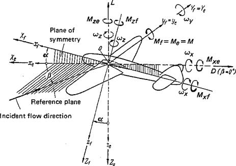
Further forces and moments, systems of axes We saw that, for symmetric incident flow, the resultant of aerodynamic forces is composed of lift and drag only. In the general case of asymmetric flow, the resultant of the aerodynamic forces may be composed of three forces and three moments. These six components correspond to six degrees of freedom of the aircraft motion. We introduce two systems of axes, depending on the flight mechanical requirements, to describe these forces and moments (Fig. 1-6).
1. Airplane-fixed system: Xf, y/, Zf
2. Experimental system: xe, ye, ze
The origin of the coordinates is the same in the two systems and is located in the symmetry plane of the aircraft. Its location in this plane is chosen to suit the specific problem. For flight mechanical studies, the origin is usually put into the aircraft center of gravity. For aerodynamic computations, however, it is preferable to put the origin at a point marked by the aircraft geometry. In wing aerodynamics it is advantageous to choose the geometric neutral point of the aircraft, as defined in Sec. 3-1.
The lateral axes of the experimental system of axes xe, ye, ze and of the system fixed in the airplane Xf, yf, Zf coincide so that ye = У/. The experimental system is obtained from the airplane-fixed system by rotation about the lateral axis by the angle a (angle of attack) (Fig. 1-6). .
For symmetric incident flow, the aerodynamic state of the aircraft is defined by the angle of attack a and the magnitude of the velocity vector. For asymmetric incidence, the angle of sideslip /3[2] is also needed. It is defined as the angle between the direction of the incident flow and the symmetry plane of the aircraft (Fig.
1- 6).
|
Figure 1-6 Systems of flight mechanical axes: airplane-fixed system, Xp yp zp experimental system, xe, ye, ze; angle of attack, a; sideslip angle, jS; angular velocities, cox, wy, ojz. |
Forces and moments in the two coordinate systems are defined as follows:
1. Aircraft-fixed system:
Xf axis: tangential force Xf, rolling moment MXf У/ axis: lateral force Yp pitching mdment Mf (or My/) ip axis: normal force Zp yawing moment MZf
2. Experimental system:
xe axis: tangential force Xe, rolling moment Mxe уe axis: lateral force Ye, pitching moment Me (or Mye) ze axis: normal force Ze, yawing moment Mze
The signs of forces and moments are shown in Fig, 1-6.
It is customary to use lift L and drag D in addition to the forces and moments. They are interrelated as follows:
L = – Ze D = – Xe (for (3 = 0) (1-19)
Further, because of the coincidence of the lateral axes y/ = ye,
Yf= Ye Mf = Me =M (1-20)
Dimensionless coefficients of forces and moments For the representation of experimental results and also for theoretical calculations, it is expedient to introduce dimensionless coefficients for the moments and forces defined in the preceding paragraph. These coefficients are called aerodynamic coefficients of the aircraft. They are related to the wing area Aw, the semispan 5, the reference wing chord cM (Eq. 3-5b), and to the dynamic pressure q ~ pV2 J2, where V is the flight velocity (velocity of incident flow). Specifically, they are defined as follows.
|
Lift: |
L = clA ц/q |
|
Drag: |
D = cD A wq |
|
Tangential force: |
X= cxAwq |
|
Lateral force: |
Y=cyAwq |
|
Normal force: |
Z = czA wq |
|
Rolling moment: |
■— ці sq |
|
Pitching moment: |
M = СмАц/c^q |
|
Yawing moment: |
Mz = cMzAwsq |
A measurement that determines the three coefficients cL, cD, and cM as a function of the angle of attack a is called a three-component measurement. The diagram cL(cD) with a as the parameter was introduced by Lilienthal [1]. It is called the polar curve or the drag polar. If all six components are measured, for example, of a yawed airplane, such a test is called a six-component measurement. Normally, the coefficients of forces and moments of aircraft depend considerably on the Reynolds number Re and the Mach number Ma in addition to the geometric data. At low flight velocities, however, the influence of the Mach number on force and moment coefficients is negligible.