Extension of the Theory to Non-straight Lifting Lines
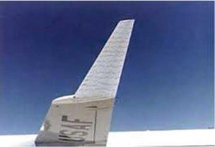
Prandtl lifting line theory has been used to analyze wing/winglet combinations and, in inverse mode, to help design wings and winglets for practical low-speed aircraft applications. The seminal work of Munk [4], a student of Prandtl in Gottingen, paved the way to understanding the contributions of these small elements placed at 90° to the main wing, which clearly do not contribute to lift, but are shown to improve the wing efficiency by decreasing the induced drag of the main wing. In Fig. 6.24, winglets are equipped with tufts to analyze the flow field during flight.
For large aspect ratio wings, the theory can be extended to lifting lines having kinks as in the case of winglets, or having a continuous curvature that turns its direction ±90°, for so-called “blended winglets”, or also being turned in the flow or against the flow direction for backward or forward sweep, as well as combinations of those. All cases have been considered by Munk, for single lifting line and multiple lifting lines. The vortex sheet takes the shape of the base surface, touching the lifting line, considered the base line. The rolling-up of the sheet edges is again neglected in the mathematical model.
JJC [5] has developed an optimization code that calculates the optimum circulation distribution along a lifting line that has a kink, for the design of winglets.
In order to find the wing/winglet combination that has the minimum induced drag for a given lift, the following objective function F(F) = CDi + ACL is defined. CDi is the induced drag coefficient. A is the Lagrange multiplier that governs the target lift. CL is the lift coefficient and is added to the objective function as a means of enforcing the lift constraint. Let a be the dimensionless winglet height normalized
|
with the semi-span, b/2. The lift and induced drag coefficients are
|
|
|
|
|
|
![]()
AR f1+a
Cot = — Г (a)qn(a)da (6.90)
2 -1-a
where a is the curvilinear abscissa along the dihedral shape, and qn is the induced velocity component perpendicular to the dihedral line in thex = 0 plane, with qn = w the usual downwash along the main part of the wing, qn = v on the left winglet and qn = —v on the right winglet. The “normalwash”, qn, depends linearly on Г as
|
|||
|
|
||
All quantities have been made dimensionless with the half span, b/2, and the incoming flow velocity aligned with the x-axis, U. The area of reference is the projected wing area, S. The minimization equation is a function of Г only, in this inviscid model, and is obtained by taking the Frechet derivative of the objective function, which reads
dF d CDi dCL
(6Г) = — (6Г) + X L (6Г) = 0, V 6Г
дГ( ) дГ ( ) + дГ ( ) ’
|
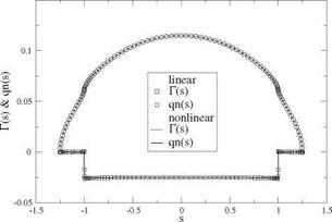
Fig. 6.25 Circulation and normalwash distributions for the optimum wing with 25 % winglet (analysis) |
The boundary conditions are Г(-1 – a) = Г(1 + a) = 0. The Frechet derivative can be defined as
d
lim {F (Г + 96Г)} (6.93)
9^0 dd
and is termed “the derivative of F w. r.t. Г in the direction 5Г”. The result is linear in 5Г.
Since CDi is homogeneous of degree two in Г and CL of degree one, the minimization equation is linear non-homogeneous in Г when X = 0. The solution is obtained in two steps: first the Lagrange multiplier is set to an arbitrary non-zero value, say X = 1 and the corresponding circulation and lift CL are calculated. Then, the final answer is obtained by multiplying the circulation by к = CLtarget/CL.
As a test case, a wing with 25% vertical winglets is designed and then analyzed for a lift coefficient Cuarget = 1. The results for the circulation and “normalwash” are shown as solid symbols in Fig. 6.25, for a selected geometry (zero twist, constant relative camber) corresponding to the optimum circulation and linear or nonlinear lift curves. The computation uses a fine mesh of jx = 101 points, including the winglets, with a cosine distributions of points on each element. This is required because the normal induced velocity is singular at the wing/winglet junction for the optimization equation, and small mesh steps are needed there. It can be noted that the winglets do not contribute to the induced drag as the normal induced velocity qn is zero at the winglets, which is in agreement with the theory [4]. The winglets are loaded, although much less than the wing. Their role is to redistribute the loads on the wing and decrease the induced drag by lowering the root circulation and by increasing it near the wing/winglet junction. The downwash on the wing is again constant, but of smaller absolute value compared to the elliptic loading. More details on the design of the geometry can be found in Chap. 11, Sect. 11.7.


