Slots
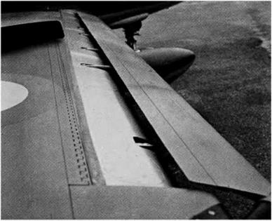
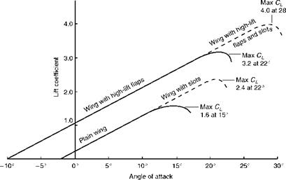
If a small auxiliary aerofoil, called a slat, is placed in front of the main aerofoil, with a suitable gap or slot in between the two (Fig. 3F, overleaf), the maximum lift coefficient of the aerofoil may be increased by as much as 60 per cent (Fig. 3.33, overleaf). Moreover the stalling angle may be increased from 15° to 22° or more, not always an advantage as we shall discover when we consider the problems of landing. An alternative to the separate slat, simpler but not so effective, is to cut one or more slots in the basic aerofoil itself, forming as it were a slotted wing.
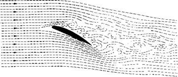
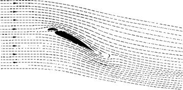
The reason behind these results is clearly shown in Fig. 3.34 (later). Stalling is caused by the breakdown of the steady streamline airflow. On a slotted wing the air flows through the gap in such a way as to keep the airflow smooth, following the contour of the surface of the aerofoil, and continuing to provide lift until a much greater angle is reached. Numerous experiments confirm this conclusion. It is, in effect, a form of boundary layer control as described earlier.
The extra lift enables us to obtain a lower landing or stalling speed, and this was the original idea. If the slots are permanently open, i. e. fixed slots, the extra drag at high speed is a disadvantage, so most slots in commercial use are
|
High-lift devices |
Increase of maximum lift |
Angle of basic aerofoil at max. lift |
Remarks |
|
Basic aerofoil |
– |
15° |
Effects of all high-lift devices depend on shape of basic aerofoil. |
|
Plain or camber flap |
50% |
12° |
Increase camber. Much drag when fully lowered. Nose-down pitching moment. |
|
Split flap |
60% |
14° |
Increase camber. Even more drag than plain flap. Nose-down pitching moment. |
|
Zap flap |
90% |
13° |
Increase camber and wing area. Much drag. Nose-down pitching moment. |
|
Slotted flap |
65% |
16° |
Control of boundary layer. Increase camber. Stalling delayed. Not so much drag. |
|
Double-slotted flap |
70% |
18° |
Same as single-slotted flap only more so. Treble slots sometimes used. |
|
V Fowler flap |
90% |
15° |
Increase camber and wing area. Best flaps for lift. Complicated mechanism. Nose-down pitching moment. |
Fig 3.32 High lift devices
Note. Since the effects of these devices depend upon the shape of the basic aerofoil, and the exact design of the devices themselves, the values given can only be considered as approximations. To simplify the diagram the aerofoils and the flaps have been set at small angles, and not at the angles giving maximum lift.
|
High-lift devices |
Increase of maximum lift |
Angle of basic aerofoil at max. lift |
Remarks |
|
~1 Double-slotted Fowler flap |
100% |
20° |
Same as Fowler flap only more so. Treble slots sometimes used. |
|
Krueger flap |
50% |
25° |
Nose-flap hinging about leading edge. Reduces lift at small deflections. Nose-up pitching moment. |
|
Slotted wing |
40% |
20° |
Controls boundary layer. Slight extra drag at high speeds. |
|
Fixed slat |
50% |
20° |
Controls boundary layer. Extra drag at high speeds. Nose-up pitching moment. |
|
Movable slat |
60% |
22° |
Controls boundary layer. Increases camber and area. Greater angles of attack. Nose-up pitching moment. |
|
Slat and slotted flap |
75% |
25° |
More control of boundary layer. Increased camber and area. Pitching moment can be neutralised. |
|
Slat and double-slotted Fowler flap |
120% |
28° |
Complicated mechanisms. The best combination for lift; treble slots may be used. Pitching moment can be neutralised. |
|
Blown flap |
80% |
16° |
Effect depends very much on details of arrangement. |
|
Jet flap |
60% |
? |
Depends even more on angle and velocity of jet. |
|
|
|
controlled slots, that is to say, the slat is moved backwards and forwards by a control mechanism; and so can be closed for high-speed flight and opened for low speeds. In the early days experiments were made which revealed that, if left to itself, the slat would move forward of its own accord. So automatic slots came into their own; in these the slat is moved by the action of air pressure, i. e. by making use of that forward and upward suction near the leading edge. Figure 3.35 shows how the force on the slat inclines forward as the stalling angle is reached. The opening of the slot may be delayed or hastened by ‘vents’ at the trailing or leading edge of the slat respectively (Fig. 3.36), and there may be some kind of spring or tensioning device to prevent juddering, which may be otherwise likely to occur. It is also important to ensure that the slots open on both wings at the same time!
Before leaving the subject of slots – for the time being, at any rate – there are a couple of interesting points which may be worth mentioning. Firstly, the value of the slot in maintaining a smooth airflow over the top surface of the wing can be materially enhanced by blowing air through the gap between slat and wing; this may be called a blown slot. Secondly, what might be called the ‘slot idea’ may be extended to other parts of the aircraft. Specially shaped cowlings can be used to smooth the airflow over an engine, and fillets may be used at exposed joints, and other awkward places, to prevent the airflow separating.
|
|
|
|

 |
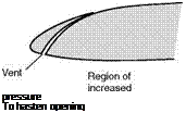 |
Fig 3.35 Direction of force on slat at varying angles of attack
To delay opening
Fig 3.36 Effect of vents on opening of automatic slots


