THE FLAT-EARTH APPROXIMATION
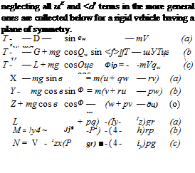
We have shown above that a wide and important range of flight dynamics problems, corresponding roughly to M < 3, can be treated adequately with a significantly simpler mathematical model than that given in Figs. 5.4 and 5.5—that is, by neglecting w® and ojf or alternatively by treating the Earth as a stationary plane in inertial space. The reduced equations obtained by
{]>———– и
![]()
![]()

![]() fl>——- »
fl>——- »
Ф——— w
■Q>—– p
{t>——- 9
0>——– r
{$>– <t>
——- *
Ф——– *
{E>—– x
{D—— m
Ф——– 6
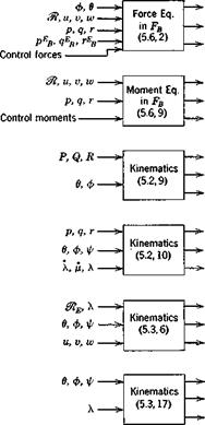
Fig. 5.5 Block diagram of equations for rigid vehicle. Spherical rotating earth. Body axis system.
 (5.8,1)
(5-8,2)
(5.8,3)
~ p if – ~f~ qic sin фц – tan Оц – – j – Tjy cos фц – tan 0jy – (a)
0 fj – = i/ff – cos ф f і – )’ц – sin </)[(‘ (b) (6.8,4)
(pjy ==: (//jj■ sin фц – – f – ( cos фц) sec Off – (c)
(Without subscript W, (5.8,4) apply to body axes.)
ax = q — qw sec ft — p cos a. x tan ft — r sin ax tan ft (a)
P = rw + P sin otx — r cos otx (b) (5.8,5)
pw = p cos іxx cos /3 + (q — ax) sin |S + r sin ax cos /3 (c)
xE=V cos 0W cos y)w (a)
yE= V cos dw sin ipw (6) (5.8,6)
ZE = —V sin 6W (c)
Xjf ~u
УЕ = I’fb ® (5-8,7)
[w
 |
 |
|
Following traditional usage, £ is used above as a symbol for both lift force and rolling moment. The context usually makes it quite clear which
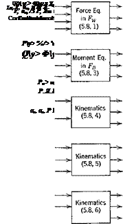
Fig. 5.6 Block diagram of equations for rigid vehicle with plane of symmetry. Combined wind and body axes. Flat-Earth approximation.
{D——- «
![]()
![]()
![]()
![]()
![]()
![]()
![]()
![]()
![]()
![]()
 {T>—— »
——- »
■П>—– ь
{0——– g
{D>—— r
——- ф
-□>———– 9
■o>—*
"U>—————- XE
"Ц> yE
■Q>————— ZE
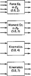
Fig. 5.7 Block diagram of equations for vehicle with plane of symmetry. Body axes. Flat-Earth approximation.
is meant, and even the novice seldom has difficulty with this ambiguity. In the nondimensional form of the equations, the ambiguity disappears, different symbols being used for the two quantities.
The block diagrams for the above equations are given in Figs. 5.6 and 5.7 for the combined and body-axes systems, respectively. Since in the case of body axes there are no kinematical relations needed to connect the two axis systems, the number of equations is twelve instead of 15. However the force equations (5.8,2) and the position equations (5.8,7) are then more complex than (5.8,1) and (5.8,6) which they replace, so the advantage resulting from the reduction of size is offset by greater complexity in the remaining members. The state variables of Figs. 5.6 and 5.7 are conveniently grouped for identification as follows:

![]() give translation of vehicle relative to Earth, give rotation of vehicle relative to Earth, give position of vehicle relative to Earth axes, give angular orientation of vehicle relative to Fv.
give translation of vehicle relative to Earth, give rotation of vehicle relative to Earth, give position of vehicle relative to Earth axes, give angular orientation of vehicle relative to Fv.
give orientation of wind axes. 6W = у is the angle of climb, and ipw is the heading of flight path.
give angular velocity of the wind axes.


