Computational (panel) methods
In Section 3.3.7, it was shown how the two-dimensional potential flow around an oval-shaped contour, the Rankine oval, could be generated by the superposition of a source and sink on the. v axis and a uniform flow. An analogous three-dimensional flow can also be generated around a Rankine body – see Section 3.4.4 above – by using a point source and sink. Thus it can be demonstrated that the potential flow around certain bodies can be modelled by placing sources and sinks in the interior of the body. However, it is only possible to deal with particular cases in this way. It is possible to model the potential flow around slender bodies or thin aerofoils of any shape by a distribution of sources lying along the x axis in the interior of the body. This slender-body theory is discussed in Section 3.4 and the analogous thin-wing theory is described in Section 4.3. However, calculations based on this theory are only approximate unless the body is infinitely thin and the slope of the body contour is very small. Even in this case the theory breaks down if the nose or leading edge is rounded because there the slope of the contour is infinite. The panel methods described here model the potential flow around a body by distributing sources over the body surface. In this way the potential flow around a body of any shape can be
see Bibliography.
|
calculated to a very high degree of precision. The method was developed by Hess and Smith[9] at Douglas Aircraft Company.
If a body is placed in a uniform flow of speed U, in exactly the same way as for the Rankine oval of Section 3.3.7, or the Rankine body of Section 3.4.4, the velocity potential for the uniform flow may be superimposed on that for the disturbed flow around the body to obtain a total velocity potential of the form
![]() Ф = Ux + ф
Ф = Ux + ф
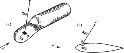
where ф denotes the so-called disturbance potential: i. e. the departure from free-stream conditions. It can be shown that the disturbance potential flow around a body of any given shape can be modelled by a distribution of sources over the body surface (Fig. 3.36). Let the source strength per unit arc of contour (or per area in the three-dimensional case) be erg. In the two-dimensional case erg dig would replace т/2тг in Eqn (3.7) and constant C can be set equal to zero without loss of generality. Thus the velocity potential at P due to sources on an element dig of arc of contour centred at point Q is given by
![]() 0Pg = uglnRpgdig
0Pg = uglnRpgdig
where Rpq is the distance from P to Q. For the three-dimensional body <7gcL4g would replace — G/(47t) in Eqn (3.63) and the velocity potential due to the sources on an element, dv4g, of surface area at point Q is given by
![]() (3.88b)
(3.88b)
The velocity potential due to all the sources on the body surface is obtained by integrating (3.88b) over the body surface. Thus following Eqn (3.87) the total velocity potential at P can be written as
Фр = Ux + §<jq In RPq6sq for the two-dimensional case, (a)
Фр = Ux + j j -~~dAQ for the three-dimensional case, (b) (3.89)
where the integrals are to be understood as being carried out over the contour (or surface) of the body. Until the advent of modern computers the result (3.89) was of relatively little practical use. Owing to the power of modem computers, however, it has become the basis of a computational technique that is now commonplace in aerodynamic design.
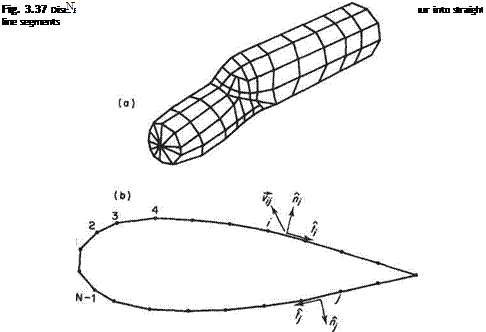
In order to use Eqn (3.89) for numerical modelling it is first necessary to ‘discretize’ the surface, i. e. break it down into a finite but quite possibly large number of separate parts. This is achieved by representing the surface of the body by a collection of quadrilateral ‘panels’ – hence the name – see Fig. 3.37a. In the case of a twodimensional shape the surface is represented by a series of straight line segments – see Fig. 3.37b. For simplicity of presentation concentrate on the two-dimensional case. Analogous procedures can be followed for the three-dimensional body.
The use of panel methods to calculate the potential flow around a body may be best understood by way of a concrete example. To this end the two-dimensional flow around a symmetric aerofoil is selected for illustrative purposes. See Fig. 3.37b.
 |
The first step is to number all the end points or nodes of the panels from 1 to N as indicated in Fig. 3.37b. The individual panels are assigned the same number as the node located to the left when facing in the outward direction from the panel. The mid-points of each panel are chosen as collocation points. It will emerge below that the boundary condition of zero flow perpendicular to the surface is applied at these points. Also define for each panel the unit normal and tangential vectors, n,- and f, respectively. Consider panels і and yin Fig. 3.37b. The sources distributed over panel j induce a velocity, which is denoted by the vector vy, at the collocation point of panel i. The components of vy perpendicular and tangential to the surface at the collocation
point і are given by the scalar (or dot) products vy • и,- and vy • (,■ respectively. Both of these quantities are proportional to the strength of the sources on panel j and therefore they can be written in the forms
Vy ■ hi = (TjNy and vy ■ /,• = ajTy (3.90)
Ny and Ту are the perpendicular and tangential velocities induced at the collocation point of panel і by sources of unit strength distributed over panel j; they are known as the normal and tangential influence coefficients.
The actual velocity perpendicular to the surface at collocation point і is the sum of the perpendicular velocities induced by each of the N panels plus the contribution due to the free stream. It is given by
N
v„i = Y/<rjNij+U-n, (3.91)
j= і
In a similar fashion the tangential velocity at collocation point і is given by
N
vSi = Y, vjTy+U-ii (3.92)
]=і
If the surface represented by the panels is to correspond to a solid surface then the actual perpendicular velocity at each collocation point must be zero. This condition may be expressed mathematically as v„, = 0 so that Eqn (3.91) becomes
N
o-yNy = – U – hfi = l, 2,…, N) (3.93)
j=і
Equation (3.93) is a system of linear algebraic equations for the Aunknown source strengths, afi = 1,2,…, N). It takes the form of a matrix equation
N<r = b (3.94)
where N is an N x N matrix composed of the elements Ny, о is a column matrix composed of the N elements cr,-, and b is a column matrix composed of the N elements — U ■ ht. Assuming for the moment that the perpendicular influence coefficients Ny have been calculated and that the elements of the right-hand column matrix b have also been calculated, then Eqn (3.94) may, in principle at least, be solved for the source strengths comprising the elements of the column matrix a. Systems of Unear equations like (3.94) can be readily solved numerically using standard methods. For the results presented here the LU decomposition was used to solve for the source strengths. This method is described by Press et al.[10] who also give Ustings for the necessary computational routines.
Once the influence coefficients Ny have been calculated the source strengths can be determined by solving the system of Eqn (3.93) by some standard numerical technique. If the tangential influence coefficients Ту have also been calculated then, once the source strengths have been determined, the tangential velocities may be obtained from Eqn (3.92). The BemoulU equation can then be used to calculate the pressure acting at collocation point z, in particular the coefficient of pressure is given by Eqn (2.24) as:
The calculation of the influence coefficient is a central and essential part of the panel method, and this is the question now addressed. As a first step consider the calculation of the velocity induced at a point P by sources of unit strength distributed over a panel centred at point Q.
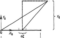
In terms of a coordinate system {xQ, yQ) measured relative to the panel (Fig. 3.38), the disturbance potential is given by integrating Eqn (3.88) over the panel. Mathematically this is expressed as follows
![]() (3.96)
(3.96)
The corresponding velocity components at P in the xq and yg directions can be readily obtained from Eqn (3.96) as

 (3.97)
(3.98)
Armed with these results for the velocity components induced at point P due to the sources on a panel centred at point Q return now to the problem of calculating the influence coefficients. Suppose that points P and Q are chosen to be the collocation points і and j respectively. Equations (3.97) and (3.98) give the velocity components in a coordinate system relative to panel j, whereas what are required are the velocity components perpendicular and tangential to panel i. In vector form the velocity at collocation point і is given by
 |
vpq = vXQij + vyQnj
AS/2
Fig. 3.38
Therefore to obtain the components of this velocity vector perpendicular and tangential to panel і take the scalar product of the velocity vector with fi, and t, respectively to obtain


