Forward Flight Effects
The effects of forward flight on aircraft noise are difficult to quantify for a variety of reasons. Even the measurement of this effect poses a significant challenge; validated predictions of the effects of flight are consequently harder. Flight testing of aircraft is very expensive and time-consuming. Several factors such as multiple engine noise sources, multiple engine configurations, engine installation effects and non-uniform flow around the engines, atmospheric propagation effects, varying weather conditions over very long propagation distances, ground reflection, and ground absorption at shallow grazing angles render even the interpretation of the measured data very difficult. Given this level of complexity, it is not surprising that there is no consensus on what constitutes a flight effect for individual engine noise components. Since the early seventies, many experimental techniques have been developed that attempt to simulate a real aircraft flyover. These have consisted of a jet embedded in a wind tunnel, a jet mounted on tracked vehicles on land, a jet mounted on a whirling rotor arm, and taxiing aircraft. Crighton et al. (1976) provide a critical evaluation of the different techniques and the advantages and disadvantages associated with each. They highlighted some fundamental issues regarding the necessity to preserve the dimensionless parameters at the model-scale and the importance of the detailed nature of the noise source and its acoustic environment, in evaluating the direct effect of flight on source strength.
Nowadays, flight effects are usually assessed by embedding a jet simulator in a free jet wind tunnel of much larger diameter, in a large anechoic chamber. Von Glahn et al. (1973), Cocking and Bryce (1975), Bushell (1975), Packman et al. (1975), and Tanna and Morris (1977) carried out some of the earliest studies. In wind tunnel tests, the microphones are located either in the tunnel flow or in the static environment outside the tunnel flow. The latter case of out-of-flow measurements are the easiest to perform and true far field measurements can be made. However, corrections are needed for the propagation of sound through the tunnel jet shear layer. Some of the factors that need to be considered in the development of these corrections are: the finite thickness of the tunnel shear layer; the axial spreading of the tunnel shear layer in the downstream direction; multiple reflections of sound waves between the jet and tunnel shear layers; the scattering of sound by turbulence in the tunnel shear layer; the background noise of the tunnel shear layer; any near field interaction of the jet and tunnel shear layers if the wind tunnel is not large enough; and a few other issues such as the possible excitation of the tunnel flow by the jet. The other major issue concerns the distributed nature of the jet sources. If there is a rapid variation of the correction factor with angle, it is necessary to place the microphones at a large distance from the tunnel shear layer so as to be able to invoke the assumption that the jet acts as a point source. The conflicting requirements of a very large wind tunnel to prevent the interaction of the jet flow with the simulator shear layer and a large anechoic chamber to ensure far field observer locations pose a tremendous problem and these requirements are not met by many facilities.
In-flow measurements avoid problems with propagation through the tunnel shear layer. However, the tunnel may not be perfectly anechoic. The problem of the tunnel flow over the microphones is also an issue. However, the biggest concern is the requirement for a very large tunnel to ensure that the microphones are in the far field, especially for a large source region.
Out-of-flow measurements are generally favored. Many of the issues mentioned above with this type of arrangement have been investigated. Amiet (1975) developed analytical expressions for the calculation of the refraction from the shear layer assuming that the tunnel shear layer could be represented by a vortex sheet. Morfey and Szewczyk (1977a) examined the various issues and recommended some guidelines for the proper choice of tunnel size, jet and tunnel operating conditions, to assure good quality of data. The scattering of sound by the turbulence of the tunnel shear layer was shown to be negligible. This proposed correction procedure was used by Tanna and Morris (1977) to interpret their data. Amiet (1978) evaluated the various correction procedures and the validity of the assumptions made in their derivations. All these methodologies attempt to convert the measured wind tunnel data to equivalent flyover conditions. Based on these ideas, the aircraft and engine companies have developed procedures to extrapolate the wind-on model scale data to full-scale flyover conditions. One of the biggest differences in these methods is the prescription of the source location for a given frequency. Empirical relations for source distributions have been derived based on theoretical considerations, acoustic mirror measurements, microphones located at multiple sideline arrays, and a combination of in-flow and out-of-flow microphones. In the multiple sideline array technique, data from each array are extrapolated to a common larger distance, with an assumed source distribution. Through proper modification of the source locations, the difference between the two sets of extrapolated data is driven to an acceptable tolerance. However, when a novel suppressor nozzle is tested, this process has to be repeated since the source distributions could be very different. Not unexpectedly, the same data processed by different procedures yield slightly different noise estimates. This is not to say that there are fundamental problems with these methods; rather, that the complexities are addressed and treated in different ways.
Norum and Shearin (1988) made extensive measurements of the far field acoustic characteristics and the plume fields of supersonic jets in an open wind tunnel with a tunnel Mach number range of 0.0-0.4. Their study indicated that there were three effects of flight on broadband shock noise. There was a lowering of the peak frequency with flight Mach number. Also, the spectral peak became narrower and several higher-order peaks became prominent with increasing flight speed. Norum and Brown (1993) extended the range of tunnel Mach number by using a free jet of diameter 0.30 m, and performed detailed aerodynamic and acoustic measurements from small convergent and C-D nozzles (Dj = 1.90 cm). The Mach number of the free jet was as high as 0.9. They noticed that the plume characteristics could be altered significantly when the free jet Mach number was increased to higher values. Even for the C-D nozzle at its design Mach number, weak shocks were observed at a flight Mach number of 0.6. With further increase in freestream Mach number, the strength and extent of the shock-containing region increased dramatically. Norum and Brown attempted to isolate the effects of source strength modification, convection due to the freestream and refraction by the shear layer as the flight speed was increased. They reported that the change in source strength for the shock noise was minimal, while the convection effect was very strong. A decrease in peak frequency of broadband shock noise was also observed with increasing flight Mach number. Finally, the effect of flight on turbulent mixing noise showed a monotonic decrease in amplitude with increasing flight Mach number at all frequencies.
The effects of forward flight on the OASPL is usually characterized in terms of the flight velocity parameter к = 10log10 [Vj/ (Vj – Vt)] where Vj is the jet velocity and Vt is the tunnel or flight velocity. Early studies by Tanna and Morris (1977) and Michalke and Michel (1979) suggest an exponent of 5 to 5.5, especially at 90 degrees. This was argued by Tanna and Morris (1977) to be consistent with the reduction of the turbulence intensity with forward flight as measured by Morris (1976). This value has been
 |
 |
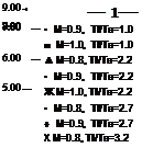
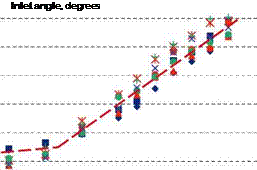
Figure 14. Variation of the relative velocity exponent with radiation angle; various jet conditions (From Viswanathan and Czech (2011)).
used in noise prediction methods to account for the effect of forward flight: for example the ARP876 by SAE (1994). However, recent measurements by Viswanathan and Czech (2011) show a lower value of velocity exponent at sideline angles with a steadily increasing value from inlet angles of 110 degrees. Figure 14 shows this variation of velocity exponent with radiation angle for various jet operating conditions. The reason for this difference could be contamination by the free jet noise and facility noise in the previous experiments: particularly at low jet exit velocities. Viswanathan and Czech (2011) removed any spectra that showed evidence of these effects in determining the velocity exponent. However, this lower exponent is not consistent with the measured reductions in turbulence intensities with forward flight. This remains a question to be resolved by both measurements and simulations.


