Implications of VRS on Flight Boundary
The adverse conditions associated with VRS mostly occur within a boundary confined to a part of the flight envelope at low forward airspeeds and at steep angles of descent or high rates of descent – see Fig. 5.33. Such results, however, are not general and the VRS boundary is known to be helicopter specific. In all cases, however, the unsteady flow conditions obtained during flight in or near VRS may result in highly unsteady blade airloads, significant rotor vibrations and unpredictable, aperiodic blade flapping. The blade flapping can lead to substantial loss of control effectiveness and high piloting workload. The rotor thrust fluctuations (see Fig. 5.31) usually lead to low-frequency vertical vibrations and an unpleasant bouncing of the helicopter. While operation in the VRS is obviously undesirable, it can be entered inadvertently through poor piloting technique. Recovery is usually attained quickly, however, by the application of cyclic control inputs to cause some increase in forward or sideward airspeed to sweep the recirculating wake away from the rotor disk.
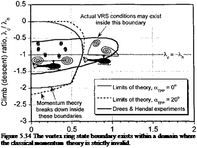
Instrumented flight tests documenting the VRS behavior of helicopters are sparse, mainly because it is a difficult flight condition to sustain any form of equilibrium flight. The flight tests of Brotherhood (1949), Stewart (1951), and Scheiman (1964) have documented the highly unsteady blade loads and high rotor power requirements found during flight in the VRS. Several researchers have conducted laboratory tests with rotors operating in the VRS, although few detailed flow field measurements have actually been obtained. This has been paralleled by some limited modeling efforts to predict the flight boundaries for the onset of VRS, mostly using forms of the classical momentum theory – see Wolkovitch (1972), Heyson (1975), Peters & Chen (1982), Newman et al. (2001), and Prasad et al. (2004). While momentum theory seems to predict a reasonable lower bound of the time-averaged induced velocity at the rotor disk and also the average induced power requirements, but it is not a rigorous approach to the problem. Momentum theory based models are deficient in predicting the conditions leading to VRS because of the ambiguity in defining a single flow direction and a well-defined slipstream boundary over which to apply the governing
Forward speed ratio, i / X
 |
equations, this issue already having been discussed in Chapter 2. This problem is illustrated in Fig. 5.34 in terms of the combination of normalized rates of descent and forward flight velocity over which momentum based theories become strictly invalid, along with the VRS boundary estimated from the classic experiments of Drees & Hendal (1951).
Another limitation with the momentum theory is that it does not provide any indication as to the effects of rotor geometric parameters (e. g., number of blades, rotor solidity, blade planform, or twist) or rotor configuration (e. g., conventional, side-by-side, tandem overlapping etc.) on the VRS problem. This is a significant deficiency that must be treated by alternative mathematical models of VRS, such as based on vortex theory – see, for example, Leishman et al. (2002). It would seem that because VRS is a nonlinear function of rotor disk loading, amongst a host of other operational and geometric parameters, it would seem unwise to generalize results obtained from tests on one rotor or any given helicopter in an attempt to predict the behavior of another helicopter. The inherent flow complexity of the VRS would seem to pose a good practical problem for advanced computational fluid dynamics methods, although the challenge has not yet been taken up except using vortic – ity transport methods (see Sections 14.3 and 14.10.7). One difficulty is in preserving the fidelity of the wake to older wake ages, the wake dynamics being inherent to the problem of VRS. Further discussion of the VRS problem using free-vortex methods is made in Section 10.10.


