
Our heavyweight helicopter equal in the world does not have
In Rostov started production of the most load-lifting rotary-wing car The Russian holding «Helicopt[...]

Everything about aircrafts and helicopters. News and events in aviation worldwide. Civil, transportation, military helicopters and airplanes.

Everything about aircrafts and helicopters. News and events in aviation worldwide. Civil, transportation, military helicopters and airplanes.

Everything about aircrafts and helicopters. News and events in aviation worldwide. Civil, transportation, military helicopters and airplanes.

Everything about aircrafts and helicopters. News and events in aviation worldwide. Civil, transportation, military helicopters and airplanes.


Motion modes of the airplane After having discussed the aerodynamic forces and the moments acting on the aircraft, its modes of motion may now be described briefly. An airplane has six degrees of freedom, namely, three components of translational velocity Vx, Vy, Vz, and three components of rotational velocity cox, coy, coz. They can be expressed, for instance, relative to the aircraft-fixed system of axes x, y, z as in Fig. 1-6. The components of the aerodynamic forces, as introduced in Sec. 1-3-2, and their dimensionless aerodynamic coefficients are functions of these six degrees of freedom of motion.
The steady motion of an aircraft can be split up into a longitudinal and a lateral motion. During longitudinal motion, the position of the aircraft plane of symmetry remains unchanged. It is characterized by the three components of motion
Vx, Vz, со у (longitudinal motion)
The remaining three components determine the lateral motion
Vy, ojx, coz (lateral motion)
It is expedient for the analysis of the interrelation of aerodynamic coefficients and components of motion to break down the general motion into straight flight, as described by Vx and Vz yawed flight, described by Vy; and rotary motion about the three axes. These rotary motions are, specifically, the rolling motion cox, the pitching motion coy, and the yawing motion coz. The quantities of angle of attack a and angle of yaw j3,[3] which were introduced earlier (see Fig. 1-6), are then given by
V f V f
tan a = —- and tan (3 = (1-22)
*xf ^xf
The signs of a, jS, cox, ojy, and cj2 can be seen in Fig. 1-6. At unsteady states of flight, the aerodynamic forces also depend on the acceleration components of the motion.
Forces and moments during straight flight The incident flow direction of an airplane in steady straight flight is given by the angle of attack a (Fig. 1-6).’The resultant aerodynamic force is fixed in magnitude, direction, and line of application by lift L, drag D, and pitching moment M (Fig. 1-6). Let us now give some details on the dimensionless aerodynamic coefficients introduced in Sec. 1-3-2. For moderate angles of attack, the lift coefficient cL is a linear function of the angle of attack a:
cL = (a — a0 ) — (1-23)
where aQ is the zero-lift angle of attack and dcLjda is the lift slope. A further characteristic quantity for the lift is the maximum lift coefficient cLmax, which is reached at an angle of attack that depends on the airplane characteristics.
For moderate angles of attack and lift coefficients, the drag coefficient cD is given by
Cd = cdo +kiCL + k2c (1-24)
where cDо is the drag coefficient at zero lift (form drag). The constants kx and k2 depend mainly on the wing geometry.
For wings of symmetric profile without twist we have kx ~ 0, and thus
cd = cdo + k2c (1-25)
This is the representation of the drag polar.
The pitching-moment coefficient см is a linear function of the angle of attack a and the lift coefficient cL, respectively:
cm = cMo±^~-Cl 0-26)
where смо is the zero-moment coefficient and dcM/dci is the pitching-moment slope. The value of cM0 is independent of the choice of the moment reference
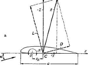
station, whereas dcMjdcL depends strongly on it. The quantity dcMjdcL is also called the “degree of stability of longitudinal motion” (rotation about lateral axis). The resultant of the aerodynamic forces of the airplane is completely determined only when its magnitude, direction, and the position of its line of application are known. These three data are obtained, for instance, from lift, drag, and pitching moment. The position of the line of application of the resultant R, for example, on the wing, can be defined as the intersection of the line of application with the profile chord (Fig. l-7a). This point is called the center of pressure or aerodynamic center of the wing. With xA, the distance of the center of pressure from the moment reference axis, we have
M=xAZ
For small angles of attack, the normal force with the negative sign is, in first approximation, equal to the lift:
Z=-L
and by introducing the nondimensional coefficients,
 xl __ cm
Cjx C%
 |
_ CM _ dcM Cm 0 cL dcL cL
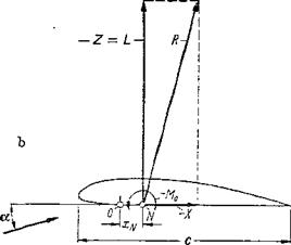 Figure 1-7 Demonstration of location of aerodynamic center (center of pressure). {a) Aerodynamic center C. (b) Neutral point N. In general, the reference wing chord is с = Сд.
This relationship means that the position of the center of pressure generally varies with the lift coefficient. The shift of the center-of-pressure position is given by the term —cmo/cl-
In agreement of theory with experiment, the pitching moment can generally be described as the sum of a force couple independent of lift (zero moment) and a term proportional to the lift:
M = M0 ~xnL
In words, the pitching moment is the sum of the zero moment and of the moment formed by the lift force and the distance xN between the neutral point and the moment reference line (Fig. 1-7Й). Again introducing the non – dimensional coefficients for lift and pitching moment:
![]()
![]() _ ■ XN
_ ■ XN
cm – cmo _ CL
CjU
Comparison with Eq. (1-26) yields, for the position of the neutral point
^N_ _ dcM CH dcL
which shows that the pitching-moment slope dCj^ldcL determines the position of the neutral point. The terms dcLjda and dc^lda. are designated as derivatives ■of longitudinal motion.
Forces and moments in yawed flight When an aircraft is in stationary yawed flight, the direction of the incident flow of the wing is determined by both the angle of attack a and the angle of sideslip 0 (Fig. 1-6). Because of the asymmetric flow incidence, additional forces and moments are produced besides lift, drag, and pitching moment as discussed in the last section. The force in direction of the lateral axis у is the side force due to sideslip; the moment about the longitudinal axis, the rolling moment due to sideslip; and the moment about the vertical axis, the yawing moment due to sideslip. The derivatives for /3=0,
/9с y / дсмЛ / ЭсмД
‘ 90/0= о 90 /0=о V 90 /0=о
are called stability coefficients of sideslip; in particular, 9c^z/90 is called directional stability. All three of these coefficients are strongly dependent on the wing sweepback, besides other influences.
Forces and moments in rotary motion An airplane in rotary motion about the axes x, y, z, as specified by the modes of motion of Sec. 1-3-3, is subject to additional velocity components that are produced, for example, locally on the wing and that change linearly with distance from the axis of rotation. The aerodynamic forces and moments that are the result of the angular velocities cox, сcy, coz will now be discussed briefly.
During rotary motion of the airplane about the longitudinal axis (roll) with
angular velocity ojx, the lift distribution on the wing, for instance, becomes antisymmetric along the wing span. The resulting moment about the x axis can be called a rolling moment due to roll rate. It always counteracts the rotary motion and is, therefore, also called roll damping. The asymmetric force distribution along the span produces also a yawing moment, the so-called yawing moment due to roll rate. Introducing the dimensionless coefficients according to Eq. (1-21), the stability coefficients of sideslip
are obtained.
The quantity Qx is the dimensionless angular velocity ojx. It is obtained from ojx, the half-span s, and the flight velocity V:
= (1-30)
The rotary motion of an airplane about the vertical axis (yaw) produces additional longitudinal air velocities on the wing that have reversed signs on the two wing halves and that result in an asymmetric normal and tangential force distribution along the wing span, which in turn produces a rolling and a yawing moment. The yawing moment created in this way counteracts the rotary motion and is called yawing or turning damping. The rolling moment is called rolling moment due to yaw rate. Again by introducing nondimensional coefficients after Eq. (1-21), further stability coefficients of yawing motion are formed:
^смх д°м2
and а<27
Here the nondimensional yawing angular velocity is
The rotary motion of the aircraft about the lateral axis (pitch), Fig. 1-6, produces on the wing an additional component of the incident velocity in the z direction that is linearly distributed over the wing chord. This results in an additional lift due to pitch rate and an additional pitching moment that counteracts the rotary motion about the lateral axis. Therefore, it is also called pitch damping of the wing. The magnitude of the pitch damping is strongly dependent on the position of the axis of rotation (y axis). By using lift and pitching-moment coefficients after Eq. (1-21), the following additional stability coefficients of longitudinal motion are obtained:
(1-32)
![]()
is made dimensionless with wing reference chord cM after Eq. (3-5b) contrary to the rolling and yawing angular velocities Qx and Qy, respectively, which were made dimensionless with reference to the wing half-span.
Only the most important aerodynamic forces and moments produced by the rotary motion of the aircraft have been discussed above. Omitted, for instance, were detailed discussions of the side forces due to roll rate and yaw rate.
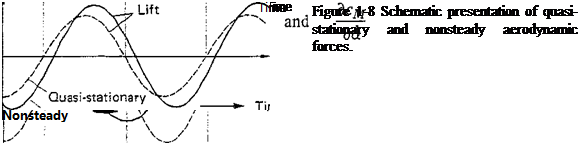
Forces and moments in nonsteady motion Besides the steady aerodynamic coefficients discussed above, the nonsteady coefficients applicable to accelerated flight have increasingly gained importance, particularly for flight mechanical stability considerations. Nonsteady motions are more or less sudden transitions from one steady state to another or time-periodic motions superimposed on a steady motion. If the periodic motion is very slow (e. g., changes of angle of attack), the aerodynamic forces can be computed from quasi-stationary theory; this means that, for instance, the momentary angle of attack determines the forces. With periodic motions of higher frequency, however, the aerodynamic forces are phase-shifted (leading or lagging) from the motion. These conditions are demonstrated schematically in Fig. 1-8 for an airplane undergoing a periodic translational motion normal to its flight path.
 |
At nonsteady longitudinal motion, new aerodynamic force coefficients must be used, for example, the derivatives
 |
where a = docjdt is the timewise change of the angle of attack. The nonsteady coefficients are important both for flight mechanics of the aircraft, assumed to be inflexible, and for questions concerning the elastically deformable airplane (aero- elasticity).
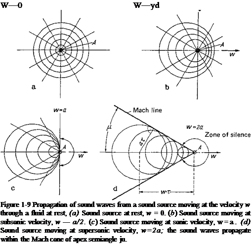
Forces and moments in supersonic flight During the transition from subsonic to supersonic flight, the aerodynamic behavior of an airplane undergoes a basic change. This becomes obvious when the airplane is taken as the source of a disturbance that moves through still air at a velocity V = w. Relative to this moving center of disturbance, pressure waves emanate with the speed of sound a. A closer investigation of this process shows the importance of the speed of sound—especially the ratio of flight velocity to sonic speed, that is, the Mach number from Eq. (1-16). In terms of fluid mechanics, the airplane can be considered as a sound source. Figure 1-9д shows the propagation of sound waves from a sound source at rest on concentric spherical surfaces. In Fig. 1-9b the sound waves, emitted at equal time intervals, can be seen for a source that moves with one-half the speed of sound, w = a[2. Figure l-9c is the corresponding picture for w = a and finally, Fig. 1-9d is for w — 2a. In this last case, in which the sound source moves at supersonic velocity, the effect of the source is felt only within a cone with the apex semiangle ju, which is given by
This cone is called the Mach cone. No signals can be sent from the source to points outside of the Mach cone, a zone called the zone of silence. No sound is heard, therefore, by an observer who is being approached by a body flying at supersonic speed. Physically, the process described is obviously identical to a sound source at rest in a fluid approaching from the right with velocity w. We have to keep in mind, therefore, the following characteristic difference: When the fluid velocity is smaller than the speed of sound (w<a, subsonic flow), pressure disturbances propagate in all directions of space (Fig. 1 -9b). When the fluid velocity is greater than the speed of sound, however (w>a, supersonic flow), pressure disturbances can propagate only within the Mach cone situated downstream of the sound source (Fig. 1-9(2).
Now, every point of the airplane surface can be considered as the source of a disturbance (sound source) as in Fig. 1-9, in analogy to the previous discussion where the whole airplane was taken as the sound source. It can be concluded, therefore, that because of the different kinds of propagation of the individual pressure disturbances as in Fig. 1 -9b and d, the pressure distribution and consequently the forces and moments on the various parts of the airplane (wing, fuselage, control surfaces) depend decisively on the airplane Mach number, whether the airplane flies at subsonic or supersonic velocities.
The above considerations show that subsonic flow has the characteristic properties of incompressible flow, whereas supersonic flow is basically different. In most cases, therefore, it will be expedient to treat subsonic and supersonic flows separately.
REFERENCES
1. Lilienthal, O.: “Der Vogelflug als Grundlage der Fliegekunst,” 1889; 4th ed., Sandig, Wiesbaden, 1965.
2. “U. S. Standard Atmosphere,” National Oceanic and Atmospheric Administration and National Aeronautics and Space Administration, Washington, D. C., 1962.
