Nozzle Flow in a “Hot” Ground-Simulation Facility
In [14], see also [15], results of a numerical study of flow and rate phenomena in the nozzle of the high-enthalpy free-piston shock tunnel HEG of the DLR in Gottingen, Germany, are reported. We present and discuss some of these results.
The computations in [14, 15] were made with a Navier-Stokes code, employing the 5 species, 17 reactions air chemistry model of Park [7] with vibration-dissociation coupling. For the expansion flow thermo-chemical equilibrium and non-equilibrium was assumed. For the description of thermal non-equilibrium a three-temperature model was used (Ttrans/rot, TVibrN2, and TVibro2). The vibrational modes of NO were assumed to be in equilibrium with Ttrans/rot, which applies to this nozzle-flow problem [14]. No-slip conditions were used at the nozzle wall, fully catalytic behavior of the wall was assumed.
Geometrical data of the contoured nozzle and reservoir conditions of the case with tunnel operating condition I, for which results will be shown, are given in Table 5.4. The nozzle originally was designed for a condition which is slightly different from condition I, therefore a weak re-compression happens around 75 per cent of nozzle length.
|
Table 5.4. Geometrical nozzle data of HEG and reservoir conditions of operating condition I [14].
|
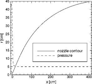
Fig. 5.7 shows the nozzle radius r(x) and the computed pressure p(x) along the nozzle axis. The expansion process is characterized by a strong drop of the pressure just downstream of the throat.
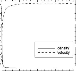
This drop goes along with a strong acceleration of the flow and a strong drop of the density, Fig. 5.8. Consequently the number of collisions between the gas species goes down. Vibrational energy will not be de-excitated, and dissociation will be frozen.
Comparing the flow variables and parameters at the nozzle exit for thermo-chemical equilibrium and non-equilibrium, Table 5.5, one sees, that the velocity u and the density p are rather weakly, the pressure p somewhat more, affected by the choice of equilibrium or non-equilibrium. This is due to the fact, that the distribution of these variables along the nozzle axis is more or less a function of the ratio of ‘pressure at the reservoir’ to ‘pressure at the nozzle exit’, and, of course, of the nozzle contour, i. e., that it is largely independent of the rate processes in the nozzle, see, e. g., [16].
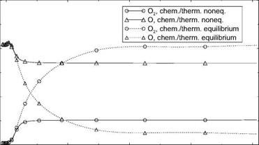
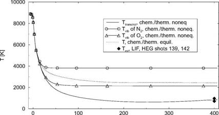
The different temperatures, Fig. 5.9, and the mass fractions—we present only O(x) and O2(x)—Fig. 5.10, however, are strongly affected by the choice of equilibrium or non-equilibrium, hence the vastly different nozzle exit Mach numbers and unit Reynolds numbers for these cases in Table 5.5.
Fig. 5.9 shows that freezing of the vibrational temperature TvibN2 happens at a location on the nozzle axis shortly behind the nozzle throat at x « 16 cm,
|
||
 |
||
|
||
|
||
|
||
|
||
|


|
Table 5.5. Computed flow variables and parameters at the exit of the HEG nozzle for thermo-chemical equilibrium and non-equilibrium [14].
|
whereas Tvib02 freezes somewhat downstream of this location at x « 23 cm. The solution for thermo-chemical equilibrium yields a temperature, Tequil, which drops along the nozzle axis monotonically, with a slightly steepening slope around x « 320 cm, due to the weak re-compression, to Tequil = 2,435.3 K at the nozzle exit.
For thermo-chemical non-equilibrium Ttrans/rot is much lower than Tequil. It drops to a minimum of approximately 550 K at x « 260 cm and rises then, also due to the weak re-compression, to Ttrans/rot = 836.3 K at the nozzle exit. At x = 400 cm, in the test section of the HEG facility, the computed Ttrans/rot compares well with measured data.
|
x [cm] Fig. 5.9. Computed temperatures along the axis of the HEG nozzle [14]. |
Freezing of the composition of oxygen in the non-equilibrium case happens on the nozzle axis at x « 18 cm, with aO, noneq ~ const. « 0.17 and ao2,noneq « const. « 0.05 downstream of x « 50 cm, Fig. 5.10. The mass fraction of atomic oxygen in the equilibrium case falls monotonically from aO, equil « 0.21 at the nozzle throat, with a slightly steepening slope at x « 320 cm, to aO, equil « 0.02 at the nozzle exit. The mass fraction of diatomic oxygen
0. 3
0. ![]()
![]()
![]()
![]()
 0
0
rises monotonically from nearly zero at the throat to ao2,equii ~ 0.21 at the nozzle exit, with a slight increase of the slope at x « 320 cm.
The fact that the equilibrium temperature Tequil is much higher than the frozen non-equilibrium temperature Ttrans, rot, can simply be explained.
We assume for both cases that the temperature in the nozzle is already so low that we can write cp = const. in the relation for the total enthalpy. We write for the equilibrium case
v2 (x)
ht = CpTpquil (x) H— —. (5.36)
If now a part of the total enthalpy is trapped in frozen non-equilibrium vibration or dissociation, it will not participate in the expansion process. Hence we get for the “active” total enthalpy h’t:
![]() ht < ht.
ht < ht.
With
v’2 (x)
h’t = cpT'(x) + , (5.38)
and v’ « v—because, as we saw above, the velocity is only weakly affected— we obtain finally the result that the temperature in frozen non-equilibrium flow, Ttransrot, is smaller than that in equilibrium flow:
As we have seen above, this effect can be very large, i. e., a significant amount of thermo-chemical energy can freeze in non-equilibrium during expansion in the nozzle of a high-enthalpy tunnel. The model then will “fly” in a frozen atmosphere with a large amount of energy hidden in non-equilibrium vibrational degrees of freedom and dissociation, compared to the actual flight of the real vehicle through a cold atmosphere consisting of N2 and O2, where only the degrees of freedom of translation and rotation are excited. Consequently the measured data may be not representative to a certain degree. A solution of the freezing problem is the employment of very high reservoir pressure/density, in order to maintain a density level during the expansion process, which is sufficient to have equilibrium flow. This then may have been bought with van der Waals effects in the reservoir and, at least, in the throat region of the nozzle.
The freezing phenomenon can be very complex. In a hypersonic wind tunnel with a reservoir temperature of Tt « 1,400 K for the M =12 nozzle— large enough to excite vibration—de-excitation was found to happen in the nozzle near the nozzle exit [17]. The original freezing took place shortly behind the nozzle throat. The de-excitation increased static temperature (TTO = Ttrans/rot) and pressure рж in the test section of the tunnel, and decreased the Mach number MTO. Although the actual Mach-number was not much lower than that expected for the case of isentropic expansion, errors in static pressure were significant. The sudden de-excitation at the end of the nozzle was attributed to a high level of air humidity [17]: the water droplets interacted with the air molecules and released the frozen vibrational energy.


