Transonic Lifting Line Theory
Cole and Cook [18], and Cheng and Meng [19], extended classical lifting line theory to unswept and swept wings in transonic flows.
For unswept wings in incompressible flows, Prandtl derived a single singular integral equation to account for the three-dimensional effects for large but finite aspect ratio wings. At each wing section, the two-dimensional theory can be used with an effective angle of attack, aeff = a – ai, where
The local two-dimensional theory can be replaced by numerical calculations, including viscous effects as discussed before this chapter.
To account for 3-D compressibility effects, an iterative method can be adopted as follows:
(i) First, the strip theory is used to calculate the circulation Г(y),
(ii) Secondly, the induced angle of attack is calculated numerically from the Prandtl singular integral equation, modified by Prandtl-Glauert’s transformation for subsonic far field,
(iii) The local two-dimensional transonic flow calculations with effective angle of attack, at each spanwise location y, are performed independently,
(iv) The process is repeated until convergence.
According to Prandtl’s theory, the downwash and the induced angle of attack are uniform across the span for an elliptic planform (without twist). In this case, thanks to similarity, only one section needs to be calculated.
In Hafez [20], numerical calculations confirm this result for both subsonic and transonic flows. The effective angle of attack is given by
aeff = a2D eAR + 2 ’ в =УІ1 – M0 (6Л68)
The corresponding formulas for the lift slope are dCL AR
— = 2эт^ + 2 (incompressible) (6.169)
![]() dCL 2n pAR
dCL 2n pAR
= (subsonic)
da p pAR + 2
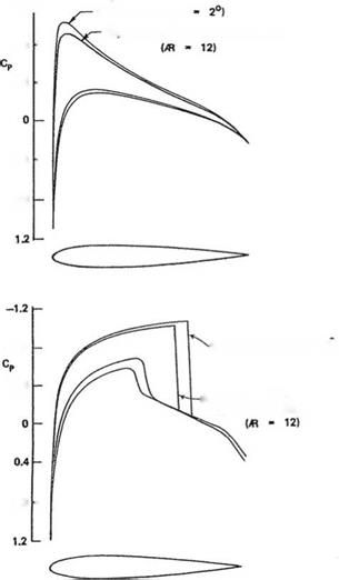
The following results of Ref. [20], confirm the validity of the above formula. The pressure distributions at the midspan for an elliptic planform (AR = 12) for M0 = 0.85 and a = 2°, are plotted for 2-D, corrected 2-D and 3-D calculations. The latter two sets are indistinguishable, see Fig. 6.40.
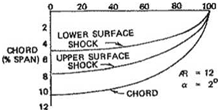
For the transonic case, the shock locus of 3-D flows for both upper and lower surfaces are plotted showing elliptic distributions, Fig.6.41.
The three calculations are produced from NASA full potential codes.
The transonic small disturbance theory for 3-D is based on the von Karman – Guderley equation
where ф is the dimensionless perturbation potential.
 2D SOLUTION (a
![]()
![]()
3D, CORRECTED 2D SOLUTIONS
0.8 –
Fig. 6.40 Top Surface pressure distributions at mid-span, M0 = 0; Bottom Surface pressure distributions at mid-span, M0 = 0.85
The linearized boundary condition is

![]() w(x, y, 0±) дф
w(x, y, 0±) дф
U
where f ± (x, y ) represents the upper and lower wing surface coordinate. In the far-fleld, the potential vanishes.
Across the wake there is a jump in potential to guaranty the continuity of pressure, ignoring the vortex sheet roll-up.
The lift is given by integration of surface pressure which reduces to the integration along the lifting line, of the circulation
b xe 2 b
ArefCL = f2 dy f (Cp(x, y, 0-) – Cp(x, y, 0+)) dx = – 2 r(y)dy
– 2 хЫ U – 2
(6.174)
As x ^ to, the potential equation reduces in the Trefftz plane to

![]()
 |
д2ф d2ф
Across the vortex sheet, there is a jump in v = U Щ corresponding to the vortex strength Г'(y) = U < v >.
The drag is given by the integration in the Trefftz plane, where u = U Щ = 0 and on the shock surfaces. Cole and Cook [18] showed that
The first term is a non-recoverable kinetic energy in the Trefftz plane representing induced drag. The second term is the wave drag evaluated in terms of “entropy” production at shock surfaces, which would have been produced if the nonisentropic shock jump conditions were enforced.
For given lift, elliptic loading is optimal, provided shocks are not strengthened.
Cheng andMeng [19] analyzed oblique wings using swept lifting line and analogy of 3-D formulation and unsteady two-dimensional flows.
For practical applications, the full potential equation, with exact boundary conditions, is solved numerically. Artificial viscosity is needed in the supersonic regions for numerical stability and to prevent the formation of expansion shocks as shown by Jameson [21], Caughey [22] Holst and Thomas [23] and Hafez et al. [24, 25]. The latter are admitted by the potential equation based on isentropic relation.


