V — TRAI LING-EDGE WING FLAPS
2. LIFT CHARACTERISTICS OF SLOTTED FLAPS
To postpone flow separation from the back of deflected flaps, boundary-layer control by means of a slot, opening ahead of the flap nose has been found useful.
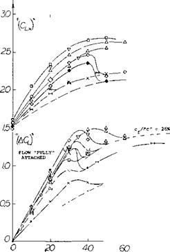
Single-Slotted Flaps. In a systematic investigation of slot shapes (15,a) the one designated as “2-h” (with a somewhat extended upper lip) was found to provide the highest lift— combined with the lowest drag coefficients. To obtain the optimum positions shown in figure 14, a complicated kinematic system is required;simple rotation about a suitable hinge point is not optimum for all angles of attack and of deflection encountered during takeoff, climb and when landing an airplane. Lift increments both for fixed hinge point and for optimum positions, are indicated in figure 14. These increments are appreciably higher than those for plain or split flaps (in figures 3 and 6, respectively). However, there is a limit above 5 = 40 , where separation evidently takes place. Other flaps of the slotted type, shown in figure 15, show a deterioration of [51]
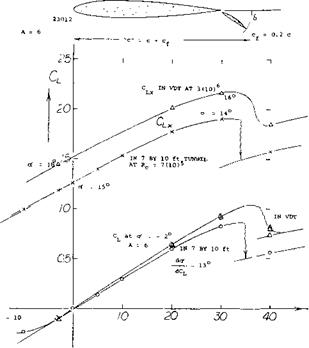
External Flaps. It has been mentioned (under “flow pattern”) that a way of substantially improving the performance of flap slots, is to make their entrance long and flat. In the extreme, this design procedure leads to the “external” flap, developed at one time by Junkers (17,e) under the name of Doppelflugel (double wing). As suggested in figure 1, structural strength necessitates a larger thickness ratio of the “main” airfoil section. The combination of main airfoil and flap must be considered to be the lifting wing. Characteristics of such a wing with A = 6, are presented in figure 16. The fact that tests in the NACA’s Variable-Density Tunnel produce a high lift-curve slope (at оC = —2°) may be attributed to the turbulence level in that: facility. The flow past the flap breaks down between 30 and 40 deflection. In aerodynamic respect, the external flap can also be considered to be a Fowler – type.
|
|
(17) Characteristics of external flaps:
a) Wenzinger, 23012 Airfoil Between Walls, NACA TRpt 614 (1938).
b) Reed, Fairchild Airplane With 23015 Wing, NACA TN 604 (1937).
c) Platt; 23012 Airfoil, Also With Roll Control, NACA TRpt 541 (1935).
d) Platt; 23012 and 21 Wings, also in VDT Tunnel, NACA TRpt 573 (36).
e) Billeb, Junkers Doppelflugel, Luftwissen Janaury 1935; Translation in “The Aeroplane” 1935 p 269.
f) Bradfield, Junkers Type Ailerons, ARC RM 1583 (1934).
|
|
|
|
|
|
|
|
|
|
|
|
|
|
|
|
|
|
|
|
|
|
|
|
|
|
|
|
|
|
 |
|
|
|
|
|
|
|
|
|
|
|
|
|
|
|
|
|


![]()
Figure 15. Lift increments (ACL) and maximum lift coefficients of various slotted flaps in two-dimensional flow, as function of their angle of deflection.
an effective lift coefficient
“CL ” = CL /(1 +cf/c)
(19)
 |
 |
Flaps for takeoff
a) Wimpress, Short takeoff and landing for aircraft, A&A Feb. 1966
b) Title 14 – Aeronautics and Space, Code of Federal Regulations 1974
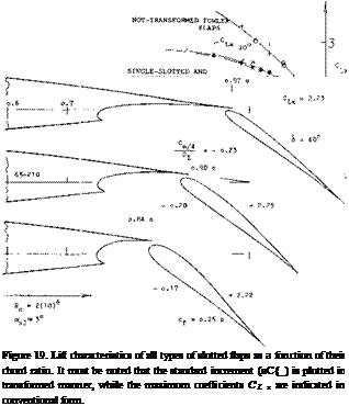
Extended Slot Lip. Fowler flaps have the disadvantage of producing large nose-down pitching moments. It is possible, however, to go “half’ way, such as in the extended-lip flaps show in figure 18. Using the transformation explained above, their lift coefficients are also included in figure 16; and all types of slotted flaps are evaluated in figure 19 as a function of their chord ratio. Extended-lip flaps reach a critical angle, at 6 between 30 and 45°, where flow separation takes place. There is evidence, however, to the effect that these flaps are superior to the simple type, at S = 30*. At this angle, their lift increment is some 20% higher than that of the simple flaps. It is assumed that the long and flat slot entrance, made possibly by translation, produces a better flow through the slot with consequent better boundary layer control on the upper side. There are similar critical angles and/or lift coefficients found in the maximum lift coefficients. After separation, the “viscous” drag is higher, but CLX resumes rising after a dip, in a manner similar to that of airfoils with plain or split flaps as in figures 3 and 6, respectively.
II. PERFORMANCE OF WINGS WITH FLAPS where 20 = 180/тґ2 = 18.2°, plus some 10% accounting for non-elliptical distribution across the span and other effects (such as round tip shape, for example). When using wing flaps, producing maximum lift coefficients above 3, at an angle of attack approaching 30°, equation 20 may no longer be adequate. First, theory shows that CL = 2ЇЇ sine* in two dimensional flow. This leads to the first term of equation 20 or 10 ~ 180/2Тґг 0.9 where 0.9 accounts for boundary-layer losses of circulation. Using the sine for o’ = 30° we find a reduction of lift by almost 5%, in two-dimensional flow. At any rate, it is clear that equation (20) cannot by used for lift coefficients approaching the simple theoretical limit for plain airfoils, of CL = 2ТҐ, see Chapter IV as we can obtain for example, when using airfoils and flaps with boundary-layer control. Theoretical limits of circulation have been considered; and they are summarized in Chapter IV and (1 ,f). It is believed that the maximum (average across the span) circulation obtainable corresponds to
CL,„~ 1-9A (22)
Considering “powered” lift such as in the jet flap, the circulation component of lift (but not the jet-reaction force) may be expected to conform to this equation as discussed later in conjunction with figure 39.
![]()
In conventional airplanes, landing flaps seldom cover the entire wing span as the wing tips have to be reserved for ailerons. As a consequence the performance of wings with flaps is somewhat different form that given for two dimensional sections in the first section of this chapter.


