CHAPTER VI — LEADING-EDGE HIGH-LIFT DEVICES
An important (or predominant) limitation of lift to be obtained in wings, is flow separation from the leading edge. Means of preventing or postponing such separation are, the use of leading-edge slots or slats, camber or the deflection of nose flaps, and boundary-layer control (blowing or by suction).
These devices are used to increase the maximum lift and/or to prevent stalling from the wing tips, thus preserving lateral (aileron) control. All types of leading – edge lift-increasing devices function by increasing the angle of attack where stall takes place. They thus control separation, while lift (circulation) is basically controlled by the position of the trailing edge (by angle of attack, with or without a flap).
|
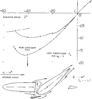
Figure 1. Horizontal-tail configuration tested (1) in a two-dimensional water tunnel; influence of a slot forme і between elevator nose and fixed auxiliary airfoil on the negative lift in the landing condition of an airplane. |
I. INFLUENCE OF SLOTS AND SLATS ON LIFT
Slots or slats are an effective means of preventing or postponing separation from the leading edge and they may help to postpone separation from the trailing edge. There are generally three types of leading edge devices;
1) fixed slots near the leading edge,
2) auxiliary airfoils ahead and above the leading edge,
3) extendable or automatically moving slats.
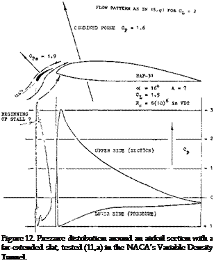
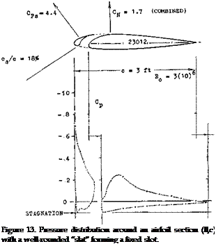
Principle. Boundary-layer control by means of a slot (such as in slotted trailing-edge flaps) is based on the concept of injecting momentum into a “tired” boundary layer. Near the leading edge of a wing the boundary layer is small however. In addition to the supply of momentum to the boundary layer the following mechanism seems to be important for the effectiveness of leading-edge slots or slats. Considering airfoil plus slat to be an entity, it is seen in figure 13, that the peak of the negative pressure distribution, is loaded onto the slat. Peak and subsequent positive pressure gradient on the “main” part of the airfoil, are thus appreciably reduced. Whatever boundary layer is formed along the upper side of the slat, is carried downstream as a thin sheet between the outer flow and the “jet” of fresh air exiting from the slot. In other words, the thickness of the boundary layer developing along the upper side of the airfoil, is reduced by the presence of a slot or slat. Still another important property of slots is demonstrated in Chapter V on “trailing-edge devices” (for all types of slotted flaps) or in figure 1 that is in a converging slot (as in a nozzle) an equalization of total pressure takes place, even though there may be a heavy boundary layer and/or separation at one side of their entrance. As a consequence, the efflux of momentum is comparatively uniform; and such slots are a suitable means of feeding momentum into the boundary layer at the upper side of flaps or airfoils. In the horizontal-tail configuration, as in figure 1 the maximum value of the negative lift coefficient is thus increased from 1.0 to 1.7.
(1) Hoerner, Investigation of a Horizontal Tail Configuration, Fiesler Water Tunnel Rpt 14 (1939).
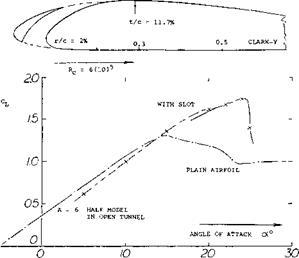
Fixed Slots. In the period of airplane development after 1930 efforts were undertaken to avoid or to reduce the structural complications of movable slats (see later). A fixed slot can be obtained simply by cutting a passage through the nose of and airfoil. With fixed slots such as shown in figure 2 the lift continues to increase above the angle of attack where the original plain wing stalls. Here as in the case of slats the lift at smaller angles at attack is somewhat lower than that of the plain airfoil. Similar results are reported in (2,b) for the more modern 23012 section. Leading-edge slots have been combined with other slots placed along the chord (2,c) eventually forming a cascade of vanes (2,c) and/or a combination with a trailing-edge slotted flap. Maximum lift coefficients up to the order of 4 have thus been obtained. However because of the lower structural design (strength) and performance at the low lift coefficients of high-speed flight such arrangements cannot be considered to be practical.
Drag. Assuming that a fixed slot would be effective by postponing separation and increasing lift its presence will increase the wing drag in the cruising and/or high-speed operation of an airplane. By rounding the leading edge of the main airfoil, the drag can be kept “low”. Fcr example, the coefficient of the shape as in figure 2, is in creased by ACos 0.01, in cruising condition, at CL = 0.3 (and up to CL = 1.0). When designing (around 1937) the Fieseler “Stork” (3) which would today be called a STOL aircraft, the principal requirements were low weight (aided by structural simplicity) combined with high lift. It was, therefore, decided to use a slat or slot of the conventional shape (3,a) and to leave it in extended position, accepting the added drag when flying at lower lift coefficients (such as at cruising speed). Water-tunnel tests reported on page
6- 14 of “Fluid-Dynamic Drag” revealed, however, that there is a minimum of sectional drag associ^ed with a fixed slot, provided that there is no flow through the slot (between slat and wing). The angle of attack where this flow pattern was obtained, could be controlled by slightly adjusting the trailing-edge wing flaps. As reported in (3,b), the section-drag coefficient of the wing was thu s reduced from CD5 = 0.030 to 0.018, at CL = 0.3; and this magnitude was considered to be acceptable in a STOL-type airplane such as the “Stork”. Even at the optimum lift coefficient (where the flow through the slot is smooth) slats produce some additional drag; the differential is in the order of ДСоэ = 0.01.
(2) Airfoils with fixed leading-edge slots:
a) Handley Page in “Aeronautical Journal” 1921 p 270.
b) Weick, Clark-Y Wing With Fixed Slots, NACA TRpt 407 (1932).
c) Weick, Multiple-Slotted Clark-Y Airfoil, NACA TRpt 427 (1932).
d) Bamber, 23012 With Several Forms of Slots, NACA TN 702 (1939).
|
s/c = 2%
Figure 2. Example for a fixed slot cut into an airfoil (2,b). |
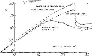
Auxiliary Airfoils. Another way of avoiding the complications of slat mechanism is to place a low-drag auxiliary “vane” ahead and above the leading edge of an airfoil, in fixed position. For maximum lift, the position of such an auxiliary foil would be similar to that of slats forming a suitable converging nozzle “around” the nose of the main airfoil. Drag at low lift coefficients however is very high. Therefore, when selecting an “optimum” position, both the lift at high angles of attack, and the drag at lower lift coefficients must be considered. Full scale tests of a fixed auxiliary airfoil on a light twin aircraft are given in (4,c) another such compromise is shown in figure 3. Performance of various configurations is claimed in (4,a)
|
to be as follows: |
|||
|
Configuration |
mm |
Llx |
Cw/C, |
|
Clark-Y plain wing |
0.015 (0.015) |
1.30 (1.30) |
86 |
|
fixed slot (figure 2) |
0.023 (0.022) |
1.75 (1.65) |
76 |
|
with auxiliary foil |
0.019 (0.016) |
1.95 (1.70) |
104 |
|
with automatic slat |
0.016 (0.014) |
1.84 (1.63) |
114 |
(3) Fieseler “Stork” Fi-156, with fixed slat or slot:
a) Krassilschikoff, Optimum Configuration (used in the “Stork”), САНІ (Moscow) Rpts 105 (1931) 133 and 161 (1934); see Luschau 1936 II (2) and (9).
b) Petrikat, “Stork” Airfoil With Slat, Fieseler Water Tunnel Rpts 6 and 12 (1939); see Ybk D Lufo 1940 p 1-248.
c) Hoerner, Flight Testing the “Stork”, Lilienthal Paper ZWB 099/006 (1938), see Luftwissen 1940 p 202; also Translation by Mississippi State College (1956).
d) The 1500 “Storks” (1939/43) were preceded by one “Gugnunc” biplane (built by Handley Page in 1928) winner of the “Guggenheim Safe Aircraft Competition”; see report on that competition, New York (1930).
e) The “Stork” has been imitated several times; see for example Pleines, Application of Slotted Wings, in (28,1). The last airplane of this type is the Dornier-27; with flaps, slats and propeller slipstream, CLX =5.3.
The numbers in parentheses are based on combined “wing” area of airfoil plus slat or auxiliary foil, while the other numbers are on Clark-Y airfoil area. — There are two objections, however, to these experimental results:
a) The Reynolds number of the auxiliary airfoil is only 9(10)4. Different optimum locations and larger lift increments may be expected at higher R’numbers.
b) Arms are needed to support any slat or auxiliary foil. They must be expected to increase drag, and to reduce lift (including its maximum).
|
|
|
Figure 3. Optimum combination (providing maximum CLy /CD mm) of and airfoil (4,a) with a fixed auxiliary foil, placed ahead and above the leading edge. |
(4) Investigation of airfoils with fixed auxiliary foils:
a) Weick, Clark-Y With Various Shapes, NACA TRpt 428
(1932) .
b) Weick, With Various Chords and Shapes, NACA TRpt 472
(1933) .
c) Fink, Fixed Auxiliary Airfoil or Slot on Lis. ht Twin Aircraft, Full Scale Test, NASA TN 7474.
(5) Investigation of airfoils with slats:
a) Wenzinger, Clark-Y Wing With A = 6, NACA TRpt 400
(1931) .
b) Jacobs, Airfoils Function of R’Number, NACA TRpt 586 (1937).
c) Weick, Fowler Flap and Slat, NACA TN 459 (1933).
d) Quinn, Combination With Flap and BL Control, NACA TN 1293 (1947),
e) Moss, Three Different Slat Chords, ARC RM 270:5 (1952).
f) Axelson, 64A010 Airfoil With Slat, NACA TN 3129 (1954).
g) Townend (NPL), Slots and BL Control, J RAS 1931 p 711.
h) Ormerod, Bristol Fighter, ARC RM 1351 (1930) and 1477
(1932) .
When calculating the wing area, aspect ratio, lift-curve slope and induced drag, it does not matter whether the basic airfoil chord, or the combined area of airfoil plus auxiliary foil is used. The pitching moment of this configuration is like a tandem system with considerable interference. For the configuration as in figure 3, the center of pressure is constant at 20% of the Clark-Y chord, between CL =0.7 and CLx, while the CP of the plain airfoil is at and aft of 30% of the chord.
Maxwell Slat. A seemingly simple slat mechanism is shown in figure 4. The moving parts operate only by rotation, about fixed hinge axes. To close the slot, the slat is turned until it touches the upper side of the airfoil, and a plate is meant to cover the inlet at the lower side. The reference wing chord is the total (including the slat). Wind-tunnel tests (6) show this configuration to be effective in regard to lift, and efficient as far as drag at small lift coefficients is concerned. There are two reasons against this type of slot, however:
1) rotation alone does not provide any optimum location of the slat,
2) structurally, the system may be as complicated as really retracting the slat.
|
OPTIMUM GAP = 3.5% c
Figure 4. Example of a so-called Maxwell slat (6,b). The slot is obtained by moving two parts about a fixed axis. |
(6) Investigation of so-called Maxwell Slats:
a) Gauvain, Clark Y Maxwell Slat, NACA TN 598 (1937).
b) Lowry, 23012 Wing With 30% Slat, NACA WRpt L-693 (1941).
c) Gillis, 23012 With 18% Slat and Flaps, NACA WRpt L-574 (1941).
d) Turner, Flight Investigation, NACA WRpt A-88.
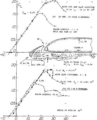
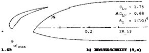
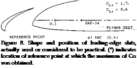
“Slats" are movable auxiliary airfoils or vanes, extended ahead of the leading edge of an airfoil to help the flow at higher lift coefficients, to get around that edge. At smaller lift coefficients (at higher flying speeds of an airplane) the slats are not needed. In fact, the drag of a far-extended and dipped slat would be prohibitive, see Chapter XVI; within the range of intermediate and low coefficients. As a consequence of separation from the lower side as shown in figure 5, drag coefficients as high as CDS = 0.1 are obtained which is in the order of 10 times that of the clean wing. Therefore, for good airplane performance slats are made retractable or automatic. Aerodynamic and kinematic development of such slats was first undertaken by Lachmann (7,d) and Handley Page, some time between 1920 and 1930. – The position of a slat in relation to the original airfoil, is defined by
a) extension forward of the leading edge,
b) downward droop or dip,
c) size of the gap at the outlet of the slot,
d) rotation or downward deflection.
|
Figure 5. Lifting characteristics of a slatted airfoil at two very different Reynolds numbers. |
Reynolds Number. For a slat the Reynolds Number based on its chord is an order of magnitude lower than that of the wing section. So, for example, if the landing of an airplane takes place at Rc = 10[52], a wind-tunnel investigation may only be conducted at 10^, and the Reynolds number of the slat would possibly be as low as Rs = 1.5 (10) , which must be considered to be critical. Wind – tunnel results on slatted airfoils obtained below 10fe, must therefore be accepted with reservation. Characteristics of a particular configuration are presented in figure 5, for two widely different R’numbers. Several discontinuities are evident for Rc ~ 7(10) ; they stem from partial separations from slat and/or upper side of the airfoil. The variation of the maximum lift coefficient as a function of Rc as in figure 6, looks rather steady. There is a discontinuity, however, around Rc = 10е*, where a second maximum takes over. One set of points (between 10to and 107) also displays a “sudden” increase of. Some slat configurations have sharp corners, both at the slat and the lower edge of the main airfoil nose. Whether intended or not, these corners might promote turbulent boundary – layer flow through the slot. It might also be tried to stimulate turbulence by trips (surface steps as in figures 8,b or 17,b, for example) or by distributed roughness (or turbulence generators; see later) placed near the outlet of the slot. Results of such tests do not seem to be available, however.
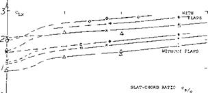
Slat Size. Maximum lift coefficients are plotted in figure 1 as a function of the chordlength ratio of the slat. Foi most of the airfoils tested, there is a sudden increase oj Сцх, at slat-chord ratios between cs/c = 0, and = 10% This increment evidently indicates elimination of leading edge separation. It is not found in cambered sections witl well-rounded noses, where such separation is not present
(8) For shapes of RAF sections (28, 38, 48, 34) see Relf, 6 Aerofoils in CAT, ARC RM 1706 (1936).
|
|
|
) ….. ……… 1————– 1————— L – о /0 20 Ю% |
Subsequently, all configurations tested, show a steady increment of Clx with the slat-chord ratio. It is suggested that lift grows simply because of the extension of airfoil chord. The average rate of growth is
AClx/си[53] [54].~ l+(cs/c) (2)
where CL# = C LX extrapolated to cs/c = zero. The rate is higher than the average in otherwise plain airfoils; and it is lower in airfoils with trailing flaps deflected. In fact, the lines in figure 7 are essentially parallel to each other. They can be expressed by
ACLX = (1.6 to 2.0) c5/c (3)


 |
 |
The argument of extended airfoil chord does not apply to the Maxwell-type of slats. Nevertheless, they show the same rate of CLX growth as the conventional type of forward-extending slats. We may have some biplane effect here.
|
c*/c |
![]()
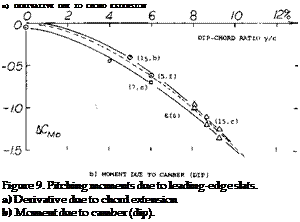 |
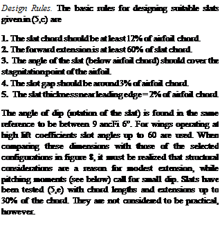
Pitching Moments. When extending a slat into the typical and most favorable position, two things happen: the effective wing chord is increased and when moving the slat down, the airfoil becomes cambered. As a consequence, the pitching moments are changed. As shown in. figure 9, there is a positive increment of dC^ /dCL , which means that the “aerodynamic center” moves forward. The forward extension of slats is usually less than their chord length. For an average A x/cg = 2/3, we tentatively obtain
(dC m/4/dCL ) = + (2/3) (cs/c) 0.75
= 0.5 (cs /с) (5)
where 0.75 = (1 – 0.25). This equation is confirmed by experimental results. As a tail-down moment, the derivative is destabilizing. The pitching moment due to camber (corresponding to droop or dip) as in part (b) of figure 9, is negative (nose-down). It thus aggravates the :rim situation caused by trailing-edge flaps. It is shown iri figure 30 of Chapter II, that the pitching moment of 230-type sections (similar in camber shape to that representing slats) increases with the camber location (x/c). A trend of ACmo~ (y/cf is seen, accordingly, in figure 9.
|
О |
|
10 |
ЗО
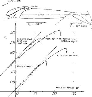
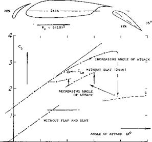
Combination With Trailing-Edge Flap. Basically, a leading-edge slat (or nose flap) increases the angle at which stalling takes place by a given increment. This increment may be the same when adding the leading-edge device to an airfoil equipped with a trailing-edge flap. The result can be expected to be a “very” high maximum lift coefficient. An example of such a configuration is presented in figure
10. There is a large hysteresis loop, reaching over some 25* of angle of attack (for A = 4). Without a slat, a 10° wide loop was found in the same test conditions. Such loops have also been found in airfoils without slats, evidently in the critical range of the Reynolds number where leading-edge separation disappears, see Chapter IV. If the hysteresis persists at larger full-scale Reynolds numbers, it can or has to be eliminated by means such as so-called double-slotted flaps (see Chapter V) or possibly by turbulence generators (on slats or ahead of trailing flaps). Another combination of slat and flap is illustrated in figure
11.
 |
Although the Reynolds number is appreciably higher than that in figure 10, the maximum lift obtained with a hardly extending flap is not higher.
|
Ю 20 ЗО 4C 50 Figure 10. Example of a combination of slat with trailing-edge flap (7,a), tested on rectangular airfoil (with A = 4) in open wind tunnel. |
 |
Combined Pitching Moments. Trailing-edge flaps produce nose-down pitching moments of a considerable magnitude. As shown in part (b) of figure 9, the moment due to dip of a slat (added to that of a flap) makes trimming of an airplane difficult. Considering “optimum” slat position producing maximum Cu , a larger dip (larger by 1 or 2% of the airfoil chord would be desirable, in combination with a flap. Some compensation by the positive derivative as in part (a) of figure 9, may help to trim an airplane; it reduces stability, however unless the flap contributes a negative component. With a Fowler flap as in (7,b) used in combination with a slat, the pitching moments are obtained at CL between 2 and 4, are of the order of Cm/4 = – 1. As a matter of interest, the “viscous” section drag is in the order of CDS = 0.1. Both these values are about 10 times what they are in an average plain airfoil section. It should also be considered that the negative lift in the horizontal tail, required to balance the pitching moment, reduces the lift gained by the lift device. This negative lift may correspond to a reduction of CLX of 0.1 or more.
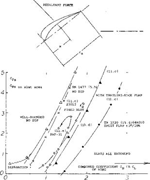
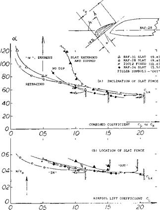
Slat Forces. As shown in figure 14, the forces (practically equal to those normal to the slat chord) might statistically be approximated by straight lines corresponding to
ACfs « ACn3 ^ K(CN or Cu ) (10)
where “s” indicates forces referred to “inclined” slat area; and CL the combined lift of the configuration referred to the basic airfoil chord or area. The factor К is between 3 and 4, for slats in extended position. Disregarding the fact that the flow separates (at lift coefficients say below 0.5, from the lower edge of a slat, provided that it remains extended) the lines in figure 14 are shifted laterally by certain values of A CL ; that is, by airfoil-section camber, by dip and/or by trailing-flap deflection. Therefore, increased dip or deflection of a trailing flap, considerably reduces the slat load (for the same lift coefficient). The maximum loads are considerable, however with or without a flap and are in the order of Crs = 4 or 5.
|
Figure 14. Slat normal forces (referred to slat-chord area) as a function of the combined lift coefficient. |
kinematic system. Therefore, direction and location (center) of the slat force (rather than its magnitude) are responsible for its automatic transfer (out and in again). — As to the location (or center) of the slat force, along its subtangent chord line, the data in part (b) of figure 15, roughly indicate a comparatively constant value around x/cs = 40%; that is at higher lift coefficients.
Inclination. Regarding direction, figure 15 shows that oC $ = 90° may be reached at Cu between 0.2 and 0.4, in “conventional” airfoil sections. The slat force then tilts forward to between 70 and 60°, at CL between 0.8 and
1.0. Upon opening (moving forward, above CL = 1.0) the angle remains essentially the same. As the lift coefficient (or angle of attack) is increased, the force tilts forward more and more, thus causing the slat steadily to move forward.
|
Figure 15. Direction (inclination) and location (center) of slat forces, as a function of the lift coefficient. |
![]()
Line of Force. To understand the nature of the slat force, it may be remembered that the tangential (chordwise) force of any airfoil section changes from positive (in the direction of drag) at smaller lift coefficients, to negative (“forward”) at higher coefficients. To move an “automatic” slat out, a force is evidently required in the direction of its chord line, or of the motion as directed by its
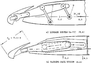
Kinematics. The mechanical mechanism permitting the slat to move, must be such that the extension takes place at higher lift coefficients (when needed) and in a smooth (continuous) manner. As illustrated in figure 17, there are two or three ways of doing this. As the angle of attack or the lift coefficient is increased, the slat forces eventually pull the slat out and move it forward. To design a smooth-working mechanism, center and direction of the slat force, as discussed above, have to be known (10).
 o) LATERALLY FOLDINS LINKAGE SYSTEM
Figure 17. Three types of mechanical mechanisms, which can be used to extend a slat, or to let it move by itself.
(9) Investigation of automatically moving slats:
a) Bradfield, RAF Airfoil Wings, ARC RM 1190 and 1204 (1928); see also same type slats in RM 1192 and 1214.
b) Jennings, Flight Tests Linkage Variation, ARC’ RM 1677 (1932).
c) Petrikat, Slats in Water Tunnel, Ybk D Lufo 19 40 p 1-248; see (3,b).
d) Lachmann, Practical Information; ZFM 1923 Issues 9 & 10 p 71; ZFM 1924 Issue 10 p 109; ZFM 1930 Issue 16 and 17. See also his book (28).
e) Braun, Optimum Slats and Slat Kinematics; Messerschmitt Rpts ТВ 33 & 34, ZWB UM 7835 (1941) and 7836 (1942). Translation of TB-33 by North American Avaiation CADO ATI-32590.
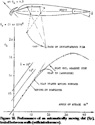
The linkage system as in figure 16 was developed (9,c) both analytically and by experiment. Assuming that the line along which the force is acting, remains constant, the motion of the slat will be steady and stable, as Jong as the instantaneous pole point (determined by the two lever lines) remains behind and/or above the force line. Forward extension and the size of the slot gap increase if the kinematic is arranged in such a manner that the pole point moves up, along the force line. Part (b) of figure 16 shows how the translation of the slat takes place:
at Cl = 0.9, the slat begins to move forward, at CL = 1.3, it reaches a limiting stop, returning, the slat is fully retracted at Cl. = 0.8.
When using a trailing-edge flap (or an aileron), start and termination of the slat motion take place at lift coefficients changed corresponding to flap deflection. Roughly, transfer (out or in) occurs at the same angle of attack.
Slot Pressure. The assumption that the slat force or at least its line of action remains constant, is not completely correct because of a certain variation of the pressure between slat and leading edge of the “main” airfoil. This pressure can become critical in the “closed” position of the slat. Average pressures corresponding to Cp = – 0.5, and up to – 1.2 are reported in (9,e) for example. Positive pressures are, on the other hand, found in (11 ,d) corresponding to Cp = + 0.1, and + 0.2, for a slat which has a small gap at the lower (pressure) side of the airfoil. A dangerous situation can arise when the trailing edge of the slat does not precisely fit onto the surface of the airfoil, thus leaving open a small gap at the upper side. The negative pressure thus developing is bound to keep the slat back up to a lift coefficient above that where it ordinarily would move forward. Subsequently, the slat will jump or pop out (suddenly) possibly banging against its stop.
Sliding Slats. In thin airfoil sections, a linkage system such as in figure 16, is structurally restricted by the wing thickness near the leading edge. The alternative solution as in part (c) of figure 17, has the disadvantage of moving the slat in spanwise direction. A more suitable design is shown in part (b) of the illustration. The slat, or a supporting pair of attachments, move along rails or tracks (by means of rollers).
(10) Some of the modern airliners (as the Boeing 707 or 727, for example) have slats installed near the wing tips. It seems, however, that any automatic function is not considered to be practical or reliable. Instead, the slats are extended together with the trailing-edge flaps, by means of an hydraulic actuator. The slats are also out during takeoff.
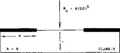
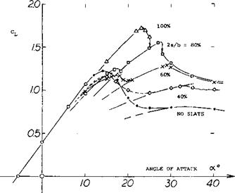
Stall Control The purpose of using leading edge slats (or slots) is twofold, to increase the maximum lift coefficient and/or to prevent wing-tip stalling. Since a large number of accidents are caused by wing stalling the use of slats can be an important safety device. When using slats to protect the wing tips, overall lift is usually not: increased. Safety and controllability are increased, however, and the operational margin of lift below the maximum can safely be reduced. In a wing with part-span slats, two* stalls take place, one at the angle of attack where the unslotted portion (in the center of the wing) loses lift, arid the other one at a higher angle of attack where the flow over the wing tips (although protected by slats) also separates. The lift of such a wing is shown in figure 18. Note there definitely is a dip between the two maximum lift conditions. For satisfactory roll stability, the lift curve slope of the outboard parts of the wing panels should remain positive. Control by means of ailerons, may still be available, up to the “very” high angle of attack where the second maximum of the lift coefficient is found. Even beyond that maximum, there is increased lift due to the presence of the slats.
|
|
|
Figure 18. Lifting characteristics of a model wing (12,a) equipped with various lengths of outboard l’edge slats. |
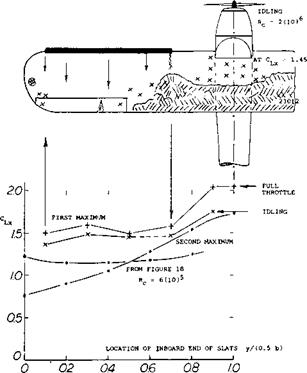
Span Ratio. The small high-wing airplane as in figure 19, was flight-tested (12,b) with various lengths of slat placed ahead of the leading edge, beginning from near the wing tips. At a constant angle of attack of 16°, total lift increases slightly with an increase in the slat length. For span ratios up to 0.6 or even 0.7, the maximum of lift reported, is evidently the first of the two mentioned above. For comparison, the maximum values of the wing in figure 18, have also been plotted in the graph. It then becomes apparent that under realistic conditions (including elevator effectiveness) the maximum lift is only really increased when extending the slats to the fuselage. A classical example of such an increment is the “Stork”; including the slipstream effect, lift coefficients were obtained (3,c) of CjJ( = 2.7 without, and of 3.9 with 40° slotted wing flaps.
|
Figure 19. Flight-tested maximum lift of a high-wing airplane (12,b) as a function of the span ratio of outboard l’edge slats. |
(11) Pressure distributions around, and loads on slats:
a) Jacobs, Slotted RAF-31 in VDT, NACA TN 308 (1929).
b) Wenzinger, Loads on Slats and Flaps, NACA TN 690 (1939).
c) Harris, 23012 With Slot and Flap, NACA TRpt 732 (1942).
d) Arabian, On Swept Wing, NASA TN D-900 (1961).
(12) Characteristics of part-span slots or slats:
a) Weick, Wing-Tip Slots, NACA TN 423 (1932); see also Lateral Control With Slots in TN 443 (1933).
b) Weick, Lateral Control in Flight, NACA TN 2948 (1953).
c) Hollingdale, Analysis Load Distribution on Tapered Wings With Part-Span Flaps and Slots, ARC RM 1774 (1937).


