CONTROL HINGE MOMENT
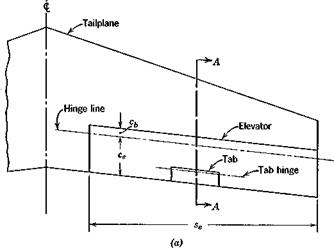
The aerodynamic forces on any control surface produce a moment about the hinge. Figure 6.21 shows a typical tail surface incorporating an elevator with a tab. The tab usually exerts a negligible effect on the lift of the aerodynamic surface to which it is attached, although its influence on the hinge moment is large.
The coefficient of elevator hinge moment is defined by
Here He is the moment, about the elevator hinge line, of the aerodynamic forces on the elevator and tab, 8e is the area of that portion of the elevator and tab that lies aft of the elevator hinge line, and ce is a mean chord of the same portion of the elevator and tab. Sometimes ce is taken to be the geometric mean value, i. e. ce = 8J2se, and other times it is the root-mean square of ce. The taper of elevators is usually slight, and the difference between the two values is generally small. The reader is cautioned to note which definition is employed when using reports on experimental measurements of Ghe.
Of all the aerodynamic parameters required in stability and control analysis, the hinge-moment coefficients are most difficult to determine with precision. A large number of geometrical parameters influence these coefficients, and the range of design configurations is wide. Scale effects tend to be larger than for many other parameters, owing to the sensitivity of the hinge moment to the state of the boundary layer at the trailing edge. Twodimensional airfoil theory shows that the hinge moment of simple flap controls
|
|
|
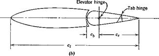
Fig. 6.21 Elevator and tab geometry, (a) Plan view, (b) Section A—A. |
is linear with angle of attack and control angle in both subsonic and supersonic flow.
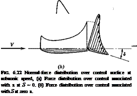
The normal-force distributions typical of subsonic flow associated with changes in a and <5 are shown qualitatively in Fig. 6.22. The force acting on the movable flap has a moment about the hinge that is quite sensitive to its location. Ordinarily the hinge moments in both cases (a) and (b) shown are negative.
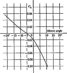
In many practical cases it is a satisfactory engineering approximation to assume that for finite surfaces Che is a linear function of a„ de, and 8t. The reader should note however that there are important exceptions in which strong nonlinearities are present. An example is the Frise aileron, shown with a typical Gh curve, in Fig. 6.23.
We assume that Ghe is linear, as follows,
![]()
 |
@he — + Ъфе + M,
where by = = Che
b — ^he — c
– he*
b = c 3 ddt hes<
as is the angle of attack of the surface to which the control is attached (wing or tail), and <5, is the angle of deflection of the tab (positive down). The determination of the hinge moment then resolves itself into the determination of 60, blt b2, and b3. The geometrical variables that enter are elevator chord ratio cjct, balance ratio cblce, nose shape, hinge location, gap, trailing-edge angle, and planform. When a set-back hinge is used, some of the pressure acts ahead of the hinge, and the hinge moment is less than that of a simple flap with a hinge at its leading edge. The force that the control system must
|

exert to hold the elevator at the desired angle is in direct proportion to the hinge moment.
We shall find it convenient subsequently to have an equation like (6.5,1) with a instead of as. For tailless aircraft, as is equal to a, hut for aircraft with tails, as = ctt. Let us write for both types
@he Gh4 + 0ЛЄха. + Ъ2де + bsdt (6.5,2)
 |
where for tailless aircraft Che<) — b0, Che^ = bv For aircraft with tails, the relation between a and oct is derived from (6.3,25) and (6.3,32), i. e.


