Improved Inviscid Flow Models
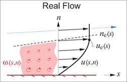
Two improved EIF models considered next are sketched in Figure 3.3. They define the EIF such that it satisfies the normal mass flux matching requirement (3.5), and thus they capture the displacement effect. The result is much better flow-field prediction accuracy, especially for flows with thick boundary layers.
3.3.1 Displacement Body model
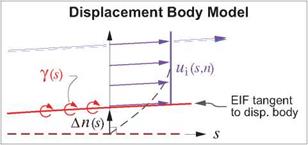
This model employs the concept of a fictitious displacement body, which is offset from the actual body by some distance An(s). The EIF is defined to be tangent to the displacement body, and hence can be constructed by a vortex sheet placed on this displacement body, as shown in Figure 3.3, rather than on the
 |
 |
Figure 3.3: Real viscous flow approximated by two improved EIF models which capture the real flow’s displacement effect. This mostly eliminates the modeling discrepancies shown in Figure 3.1.
wall as in Figure 3.1. The objective here is to determine what An(s) has to be so that the vertical mass flux matching condition (3.5) is satisfied.
 |
 |
|||
The EIF’s p[Vi in this situation is computed using the continuity equation, as for the real-flow case. Note that pivi is not zero at the displacement body, since displacement body’s normal vector is tilted away from the n axis by the slope d An/ds. The model is also assumed a priori to give the correct EIF which matches the real flow, so that we can set u; = ue.
Requiring this pivi to be equal to the real flow’s pv as defined by (3.6), gives
so that the necessary offset for the displacement body is just the displacement thickness (hence the name).


