Laminar Boundary Layer at High Reynolds Number
For the second application we solve the compressible Navier-Stokes equations at a low Mach number for a classical test case, the flow over a flat plate. We are simulating a laminar boundary layer but for a very high high Reynold number. Ludwig Prandtl and Blasius, one of his students, made pioneering achievements with their work on the boundary layer. This ended up in the solution of Prandtl’s boundary layer approximation equations by Blasius, reducing them to a nonlinear ordinary differential equation (ODE) of third order for the case of a laminar steady flow. This ODE can be solved nowadays numerically by a math algebra program with an arbitrary accuracy. We employed the software Matlab where we solved Blasius’ boundary layer equations (see e. g. [16]) with a four step Runge-Kutta scheme and a Newton-Raphson iteration method. This serves us as the reference solution for the iterated defect correction applied on the Navier-Stokes equations.
To point out the abilities of the WENO reconstruction in a reference space used in our work and the approach of the iterated defect correction we still used a fully unstructured triangular grid even in the boundary layer. For a finite volume scheme, this is a quite demanding task where surely some extra fine tuning is necessary to obtain satisfying results. One of them turned out to be the numerical flux approximation for which we took the HLLC flux as described in [20]. Our computational domain is Q = [-0.5,2]x[0,0.05] discretized by a total of 5250 triangular elements. In the interval -0.5 < x < 0 we use a slip wall boundary condition where the velocity normal to the wall is zero. At x = 0 we impose than a non-slip wall adiabatic boundary condition in the interval 0 < x < 2. The free stream Mach number is Ma«, = 0.3, resulting from the free stream flow parallel to the wall with u«, = 0.3, p«, = 1 and p«, = 1 /у. As we use the equation of state for ideal gas the ratio of the specific heats is у = 1.4, whereas the Prandtl number is Pr = 1.
 |
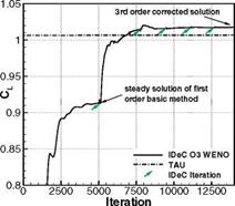
Fig. 7 Lift (left) and drag (right) coefficient computed with a first order basic method and a 3rd order defect reconstruction, compared with a second order TAU code solution on the same grid
For the chosen high Reynolds number of Re = 106 [1/m] we set our viscosity to д = 3 • 10-7 making again the assumption of a constant viscosity in the whole domain. To resolve the flow at high Reynolds numbers, which implies a very thin boundary layer of 5X=1 = 5 • 10-3 in our case, a highly stretched grid in the boundary layer is necessary. At v = 1 we therefore have cells with an aspect ratio of 1 : 205. However the chosen spacing at the first cell of y1 = 4 • 10-4 is still quite high compared to setups in the literature which are meant to be solved with a finite volume method 2nd order TVD method (see e. g. [9]). In addition we use only 8-9 cells to discretize the boundary layer at v = 1.
 |
 |
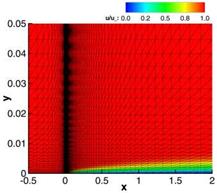
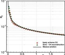
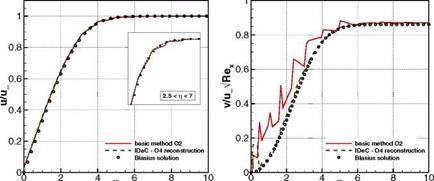
The initial condition is given by the free steam conditions and we take a homogeneous block profile with the free stream conditions at the inflow. It is important that mass can escape at the farfield, since due to the boundary layer growth we get a non-zero velocity outwards. At the outflow we can use simple extrapolation of the inner state values and impose only the free stream pressure. For the computation we used a second order basic scheme to obtain a steady solution which we reach after t = 20 seconds of simulation time. After each steady solution we apply the defect correction with a 4th order accurate WENO reconstruction again with the parameters ne = 2L, r = 6, £ = 10-14 and Xc = 105. Left in Fig. 8 we see the distribution of the dimensionless x-velocity u/u^ in the whole domain for the basic method. In addition we compare the Blasius solution with the velocity profiles of both u and v components of the velocity at the position v = 0.7 (see Fig. 9) and with the skin friction coefficient over the entire plate (see Fig. 8, right). For all comparisons the corrected numerical solution, here shown after four defect correction iterations, is in good agreement with the Blasius reference solution. At this point, we have to mention, that using a scheme of higher order with WENO reconstruction is unstable and
Fig. 8 Flat plate at high Reynolds number Re = 106 [1/m] with a = 0° and Ma = 0.3 computed with a 2nd order basic method and corrected using a 4th order WENO reconstruction. Left we show the distribution of the dimensionless x-velocity u/u^ in the whole computational domain and right the skin friction coefficient is depicted over the plate length after four defect correction iterations.
|
Fig. 9 Flat plate at high Reynolds number Re = 106 [1 /m] with a = 0 and Ma = 0.3 computed with a 2nd order basic method and corrected using a 4th order WENO reconstruction. Distribution of the dimensionless x-velocity u/uM (left) and of the dimensionless y-velocity v/u^-/Re^ (right). |
no steady solution can be obtained. The method of iterated defect correction seems to be stable, as it is based only on a second order scheme, and is nevertheless able to correct the basic method with the high order accurate defect.
For the и component we can see in the zoom made in the section of the dimensionless variable 2.5 < t] < 7 with t] =y/y^p and the kinematic viscosity
v = р/р, that we get a smoother distribution by applying the defect correction. In the case of the dimensionless v component of the velocity v/iioo/Rex with Rex = the improvement of the solution is considerable. The completely wrong distribution of the basic method could be corrected to fit quite well with the reference Blasius solution. Near the wall we nevertheless reach the limits of the reconstruction, which has shown so far that the reconstruction in the reference space can cope even with these highly stretched elements. The corrected skin friction coef – flcient (Fig. 8, right) shows also better agreement with the reference solution especially at the beginning and the end of the plate. The remaining difference is due to the stagnation point at x = 0 where high gradients occur, causing oscillations. As can be read in literature the prediction of skin friction coefficients still remain a difficult issue in the numerical simulation. Similar to [9] we compare therefore the friction coefficients at the end of the plate at x = 2. The analytical solution can again be computed by solving the Blasius equations and we get
0.664 pu^x
cf=—F= with Rex=———————————— . (41)
/Rex P
With Cf (x = 2) = 4.983 • 10~3 the error of the skin friction of the basic method is of 6.1% and with the iterated defect correction approach it could be corrected to Cf (x = 2) = 4.653 • 10~3 resulting in a remaining error of 0.9% for this case.
1.2 Conclusion
In this work we applied the method of iterated defect correction to a finite volume scheme and solved both, the Euler and the Navier-Stokes equations. A steady solution of lower accuracy, mostly of first or second order, is the starting point for the method of iterated defect correction. The next step consists of a WENO reconstruction which is used to evaluate the local defect of the steady solution. If we modify our equations by putting the local defect on the right hand side as a negative source term, the low order solution can be iteratively shifted to the accuracy of the reconstruction. The main advantage of this approach is that the high order scheme has not to be solved – the high order scheme is only used to calculate an estimation of the local discretization error. Hence, this approach can be used to increase the accuracy of an existing code in a straightforward way. It seems that the high order approximation also inherits some additional stability from the low order solver. Our results show that the iterated defect correctionin combination with the WENO reconstruction in [4] for unstructured meshes works very well. We did not succeed to define robust boundary conditions in any case. This seems to be even more subtle than the definition of high order boundary conditions in general.
We have shown numerical convergence results up to sixth order of accuracy, applying the method of iterated defect correction starting with a first order steady solution. By modifying the original approach, a relevant speed up could additionally be achieved for equations with source terms depending on the solution itself. The scheme remained stable even for the more challenging test case of the transient Ringleb’s flow. A fourth order accurate solution could be achieved here from a first order numerical scheme. Convergence studies using the manufactured solutions method have shown that in the case of the Navier-Stokes equations, where a local defect can be computed separately for the convective and the diffusive fluxes, it is crucial for flows with low Reynolds numbers to evaluate the local defect for all fluxes. Neglecting the defect in the convective fluxes still gave better absolute error norms compared to the low order solution, but the expected high order of the reconstruction was not reached for our test cases.
A RAE 2822 profile have been computed as an application test case, solving the Euler equations with a first order basic scheme applying a third order accurate reconstruction to determine the local defect. Compared to the first order solution the aerodynamic coefficients like lift and drag could be corrected by 11%, respectively 28%. As a second application test case a laminar boundary layer at a high Reynolds number of Re = 106 was numerically solved using the iterated defect correction. Better results compared with the second order starting solution could be achieved applying the defect correction combined with a fourth order reconstruction. For example a reduction of the skin friction error at the end of the plate from 6.1% with the basic scheme to 0.9% was reached in this case.


