Our heavyweight helicopter equal in the world does not have
In Rostov started production of the most load-lifting rotary-wing car The Russian holding «Helicopt[...]

Everything about aircrafts and helicopters. News and events in aviation worldwide. Civil, transportation, military helicopters and airplanes.

Everything about aircrafts and helicopters. News and events in aviation worldwide. Civil, transportation, military helicopters and airplanes.

Everything about aircrafts and helicopters. News and events in aviation worldwide. Civil, transportation, military helicopters and airplanes.

Everything about aircrafts and helicopters. News and events in aviation worldwide. Civil, transportation, military helicopters and airplanes.


Figure 2.5 illustrates the conventional main rotor collective and cyclic controls applied through a swash plate. Collective applies the same pitch angle to all blades and is the primary mechanism for direct lift or thrust control on the rotor. Cyclic is more
|
|
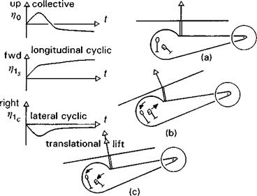
complicated and can be fully appreciated only when the rotor is rotating. The cyclic operates through a swash plate or similar device (see Fig. 2.5), which has non-rotating and rotating halves, the latter attached to the blades with pitch link rods, and the former to the control actuators. Tilting the swash plate gives rise to a one-per-rev sinusoidal variation in blade pitch with the maximum/minimum axis normal to the tilt direction. The rotor responds to collective and cyclic inputs by flapping as a disc, in coning and tilting modes. In hover the responses are uncoupled with collective pitch resulting in coning and cyclic pitch resulting in rotor disc tilting. The concept of the rotor as a coning and tilting disc (defined by the rotor blade tip path plane) will be further developed in the modelling chapters. The sequence of sketches in Fig. 2.6 illustrates how the pilot would need to apply cockpit main rotor controls to transition into forward flight from an out-of-ground-effect (oge) hover. Points of interest in this sequence are:
(1) forward cyclic (p1s) tilts the rotor disc forward through the application of cyclic pitch with a maximum/minimum axis laterally – pitching the blade down on the advancing side and pitching up on the retreating side of the disc; this 90° phase shift between pitch and flap is the most fundamental facet of rotor behaviour and will be revisited later on this Tour and in the modelling chapters;
(2) forward tilt of the rotor directs the thrust vector forward and applies a pitching moment to the helicopter fuselage, hence tilting the thrust vector further forward and accelerating the aircraft into forward flight;
(3) as the helicopter accelerates, the pilot first raises his collective (pc) to maintain height, then lowers it as the rotor thrust increases through so-called ‘translational lift’ – the dynamic pressure increasing more rapidly on the advancing side of the disc than it decreases on the retreating side; cyclic needs to be moved increasingly forward and to the left (n1c) (for anticlockwise rotors) as forward speed is increased. The cyclic requirements are determined by the asymmetric fore-aft and lateral aerodynamic loadings induced in the rotor by forward flight.
The main rotor combines the primary mechanisms for propulsive force and control, aspects that are clearly demonstrated in the simple manoeuvre described above. Typical
|
Fig. 2.6 Control actions as helicopter transitions into forward flight: (a) hover; (b) forward acceleration; (c) translational lift |
control ranges for main rotor controls are 15° for collective, more than 20° for longitudinal cyclic and 15° for lateral cyclic, which requires that each individual blade has a pitch range of more than 30°. At the same time, the tail rotor provides the antitorque reaction (due to the powerplant) in hover and forward flight, while serving as a yaw control device in manoeuvres. Tail rotors, or other such controllers on single main rotor helicopters, e. g., fenestron/fantail or Notar (Refs 2.5, 2.6), are normally fitted only with collective control applied through the pilot’s pedals on the cockpit floor, often with a range of more than 40°; such a large range is required to counteract the negative pitch applied by the built-in pitch/flap coupling normally found on tail rotors to alleviate transient flapping.