Rotor Solidity
Rotor solidity, a, has been defined previously as the ratio of total blade area to the disk area (i. e., a = Nbc/тг R). Values of о for contemporary helicopters vary from about
0. 06 to 0.12. Smaller helicopters generally tend to have lower solidity rotors. It has been shown in Chapter 3 that the mean rotor lift coefficient is given in terms of the blade loading coefficient, Ст/сг, by Ci = 6{Ct/o). Typical values of CL for helicopters range from about 0.4 to 0.7.
Selecting the rotor solidity during the design process requires a careful consideration of blade stall limits, that is the mean lift coefficient where the rotor performance will be stall limited. Certification or acceptance requirements dictate the load-factors and bank angles that must be demonstrated without the rotor stalling. Normally civil helicopters require a minimum of 1.15 g or a 30° bank angle without evidence of stall at the maximum gross weight of the helicopter. Military requirements tend to be much more severe, however. Rotors that are designed for high forward flight speeds and/or high maneuverability requirements require a higher solidity for a given diameter and tip speed. Obviously, a rotor that uses airfoil sections with high maximum lift coefficients can be designed to have a lower solidity, all other factors being equal. Alternatively, the use of high-lift airfoil sections permits a lower tip speed for the same solidity. Because rotor noise is considerably
|
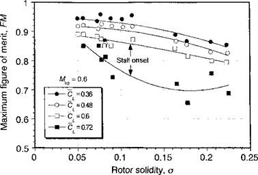
Figure 6.7 Measured figure of merit variation at different mean lift coefficients versus rotor solidity for a constant tip Mach number of 0.6. Data source: Department of the Army, Engineering Design Handbook (1974). |
reduced when the rotor is operated at lower tip speeds, the development of high-lift airfoils that operate efficiently over the diverse range of conditions found within the rotor environment has always been an important design goal for the helicopter industry – see Section 7.9.
Figure 6.7 shows experimental results for the variation in figure of merit versus rotor solidity at different mean lift coefficients. These results simply reaffirm that one way to minimize profile power is to keep the rotor solidity as low as possible. However, this approach must be done with caution because decreasing the solidity reduces the blade lifting area, increases the blade loading coefficients, and elevates the local and mean blade lift coefficients for a given rotor thrust. In other words, decreasing the rotor solidity decreases the stall margin, which is the margin between the average values of the operational lift coefficients and the maximum lift coefficient of rotor as a whole. For example, consider rotor operation at a nominal mean lift coefficient, Cl, of 0.6, as shown in Fig. 6.7. Then for a given value of solidity, operation of the rotor at a higher Cl results in a substantial degradation in rotor performance. This degradation is alleviated by increasing the solidity of the rotor, which helps reduce the local lift coefficients and improve the lift-to-drag ratios of the airfoil sections. Because the onset of stall sets the performance limits of a rotor, it is also very important to provide some additional stall margin in the rotor design to allow for normal maneuvers and gusts typical of turbulent air. The specified margin, which will vary for different helicopter designs, generally tends to set the lowest allowable solidity to which the rotor can be designed. For example, a highly maneuverable combat helicopter will always require a larger stall margin than a civilian transport machine. This is obtained, however, only with increased blade weight and higher overall rotor weight.
The onset of retreating blade stall in forward flight also limits the rotor performance. In forward flight, the rotor must provide both lifting and propulsive forces, the latter of which depends largely on the parasitic drag of the airframe but the rotor drag is also important. The stall inception boundary in forward flight can be most easily observed from strain-gauge
|
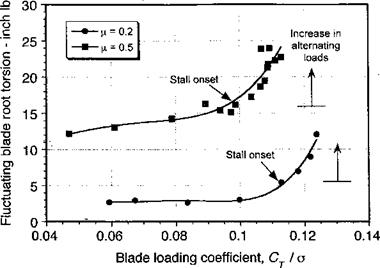
Figure 6.8 Retreating blade stall inception in forward flight deduced from blade root torsion loads. Data source: McHugh (1978). |
measurements of blade-pitch link and/or blade torsion loads. When stall occurs on the rotor, the mean (average) and alternating aerodynamic pitching moments increase dramatically. Representative measurements of the fluctuating component of the blade root torsion loads are shown in Fig. 6.8 as a function of Cj jo at two advance ratios of 0.2 and 0.5. At low advance ratios the blade root torsion loads are relatively low, but as Ct/o reaches about
0. 11, there is a more rapid increase as the rotor begins to show some evidence of stall. As the advance ratio increases, stall inception occurs at progressively lower values of Cj jo. At (Л = 0.5, the stall onset is more sudden and shows large increases in the fluctuating loads because of the onset of dynamic stall on the retreating blade. These fluctuating loads will manifest as high structural stresses in the blade and hub, and higher control forces, accompanied by significant increases of vibration levels. Stall will also cause longitudinal blade flapping, tilting the disk back (a fic blade motion) and decreasing propulsive force, therefore setting a natural barrier to further increases in forward speed. Higher control forces and the higher than normal vibration levels on the helicopter will serve as a warning to the pilot that the limits of the normal operational flight envelope of the rotor are being reached.
As already mentioned, propulsive force considerations also influence the selection of rotor solidity. In forward flight the function of the rotor is to provide a vertical lift force to overcome airframe weight as well as to provide a forward acting propulsive force. The overall envelope is summarized by Fig. 6.9, which is one type of representation of blade loading (or mean lift coefficient) versus propulsive force. The disk must be progressively tilted forward to provide this forward thrust (propulsion) component, and so stall onset will be obtained at progressively lower values of mean lift coefficient. Notice also that rotor noise issues become important in high-speed forward flight, particularly a form known as high-speed impulsive or HSI noise. Propulsive requirements can be reduced by minimizing the parasitic drag of the airframe or by thrust and/or lift compounding. While offering some advantages over a conventional helicopter, compound helicopter designs also suffer from many disadvantages as well – see Section 6.11.1.
 Propulsion Drag
Figure 6.9 Propulsive limits for a conventional helicopter. Adapted from Vuillet (1990) and other sources.


