THE LIFT DISTRIBUTION ON A RIGID WING
In previous sections the spanwise-lift distribution over a finite airfoil is generally assumed to be given by the strip theory, according to which the local lift coefficient is proportional to the local angle of attack a. This approximation is a crude one, but is sufficient for certain purpose.
* Except possibly when h2(y) is orthogonal to the eigenfunction.
To account for “induction” properly, more refined theory should be used.
For a wing with very small angle of sweep, Prandtl’s lifting-line theory may be used. In this case the local lift coefficient Cfy) is given by the following integral equation:*
![]() (1)
(1)
 |
where у is the spanwise location, afy) is the two-dimensional lift-curve slope of the airfoil section at y, and <x(y) is the angle-of-attack distribution required to produce the lift-coefficient distribution Cfy). <x(y) is the geometrical angle of attack between the zero-lift line of the section and the flight direction. Methods of solving Eq. 1 have been proposed by Glauert, Lotz, Hildebrand, Multhopp, and Sears. f For swept wings and wings of small aspect ratio (say less than 5) Prandtl’s lifting-line theory does not apply. To obtain accurate results it is necessary to use a lifting-surface theory in which an airfoil is replaced by a continuous distribution of vorticity over a surface. Unfortunately the calculation becomes involved and only a small number of solutions exist at present (see refs. 4.39, 40, 41, 44, 45, 48, 49, 50, 56). However, a modification of the Prandtl theory, known as Weissinger’s method, gives a good approximation for swept wings. In Weissinger’s method the bound vorticity of the wing is concentrated into the x/4-chord line, and the downwash is calculated at the 3/4-chord line. The condition that the down wash angle be equal to the slope of the wing with respect in the direction of flow is then applied at the 3/4-chord line. This results in an integral equation governing the lift distribution similar to Eq. 1, but with a continuous function added to the original kernel.^ Practical methods of solution are given by Mutterperl4-52 and Weissinger.4 58
A short empirical approximate method for estimating the spanwise lift distribution is given by Schrenk4-54 for a normal (unswept) wing, and is extended to sweptback wings by Pope and Haney.4 53
So far the compressibility effect is neglected. The compressibility of the fluid is expressed in terms of the Mach number M*
When the airfoil speed is subsonic (M < 1), the change in the lift-curve slope is given approximately by Glauert’s formula4 46:
ag — — ag (2-dimensional) (2)
VI — M2
 |
||
where a0 is the value of ЭСг/За for a compressible fluid, and ctg that for an incompressible fluid (M = 0), both in a two-dimensional flow. f The effect of finite span is then approximately given by the following formulas:
where a’ is the lift-curve slope of a wing of finite aspect ratio in a compressible flow, and г is the same Glauert’s correction factor for nonelliptic planform (Fig. 1.13, p. 35). For very small Ж, we have
Equation 4 yields the correct limiting value for wings of very low aspect ratio.§
77 /unswept, incompressible
Лa ~ 2 symmetric loading, Ж 0/ ^
|
(*7o)swept ‘ «0 cos A |
The effect of sweep angle is incorporated in the following formulas:
|
_____ (Vo)*wept____________ , (VoXweptV, pXweptO T) ( ttJR / ‘ ттЖ |
where a0 is the lift-curve slope of the airfoil section normal to the leading edge.
where JR is the aspect ratio b2jS (b — the wing-span from tip to tip, S = the wing area).*
If the wing is tapered, the sweep angle A should be measured along the V4-chord line. The values of т are given in Fig. 1.13 (p. 35).
For antisymmetric spanwise lift distribution, the effective aspect ratio is approximately one-half that of the entire wing. Therefore, an approximation is obtained by replacing JR in Eq. 8 by
JRe — JR/2 (antisymmetric loading) (9)
Eqs. 3, 4, 8, and 9 are useful in aeroelasticity. By means of these corrections, the errors of the strip theory are greatly reduced.
Because of the difference in the effective aspect ratio for the symmetric and antisymmetric spanwise load distributions, the corrected values of a should be distinguished for the two cases. Let the spanwise angle of attack a(y) be separated into two parts, one symmetrical in у and another antisymmetrical in y,
<У) = asym(2/) + “antisym ІУ) (Ю)
then we may write
CM = OV-ayrniy) + ««antisym ІУ) (1 0
For a, Eq. 4 or 8 can be used. For 3, the aspect ratio in Eqs. 4 and 8 should be replaced by JRe = JR/2.
The equations quoted above are not valid when the wing approaches stalling, either because of too high an angle of attack or because of too high a speed of flight. The former is stalling in the conventional sense; the latter is called shock stall, and is due to the formation of shock waves over the wing. Both involve a loss of lift and an increase of drag. Shock stall occurs when the free-stream Mach number exceeds the Mach number
* T. A. Toll and M. J. Queijo, NACA Tech. Note 1581 (1948); F. W. Diederich, NACA Tech. Note 2335 (1951).
of “divergence” MCI which is defined as the point of inflection of the curve of lift coefficient plotted against the Mach number (see Fig. 4.6 and Fig. 9.2).
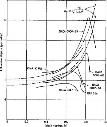
In Fig. 4.6 the lift-curve slope is plotted against M for several airfoils. It is seen that Glauert’s formula (Eq. 2) gives a fair approximation for
|
Fig. 4.6. The variation of lift-curve slope with Mach number. |
lower Mach numbers, and that, when MCI is exceeded, the lift-curve slope decreases sharply.4-37
When the free-stream Mach number is sufficiently large, both subsonic and supersonic regimes are present in the field of flow. This is the transonic regime in which both the force and moment coefficients and the angle of zero lift change substantially. The variations are too complicated to be reviewed here.
When the free-stream Mach number is larger than one, the flow is supersonic. When M is sufficiently high, the linearized theory again gives a good approximation.* Let a pressure coefficient be defined by the equation
![]() C – p ~Po
C – p ~Po
9 W/2
where p is the local pressure, and p0, p0, U refer to quantities at a large distance from the airfoil. Then, according to the linearized theory, the pressure coefficient at any point on a two-dimensional airfoil is proportional to the local slope of the surface. If the surface of a two-dimensional airfoil is represented by the function у = Y(x), thenf
where the subscript “upper” indicates the upper surface of the airfoil. The corresponding formula for the lower surface is obtained by replacing the right-hand side with a negative sign. The total lift coefficient is given ЬУ
4 t
CL =-—==- (two-dimensional, supersonic) (14)
VM:2 — 1 c
where c is the chord length, т is the normal distance between the trailing edge and the line parallel to the flow direction passing through the leading edge, r/c can be identified as the angle of attack. Hence,
a = = – г:" , = (supersonic) (15)
0 Эос /0 VM2 – 1
For a flat-plate airfoil, the slope dYjdx is constant; Eq. 13 implies that the center of pressure is at the mid-chord point.
For wings of finite span a supersonic flow differs from the two-dimensional one only in the tip region. For wings of small aspect ratio, the lifting-surface theory must be used. Many cases of lifting-surface theory have been worked out for a linearized supersonic flow.4,47
For a swept wing of large aspect ratio with a measured in the free-stream direction, we obtain, analogous to 7,
![]() ЭCL _ 4 cos Л /supersonic leading edge,
ЭCL _ 4 cos Л /supersonic leading edge,
до: */M2 cos2 Л — 1 cos Л > 1
* See for example, R. E. Bolz and J. D. Nicolaides, J. Aeronaut. Sci. 17, 609-621 (1950).
t See Liepmann and Puckett, Ref. 1.46, p. 145.


