Our heavyweight helicopter equal in the world does not have
In Rostov started production of the most load-lifting rotary-wing car The Russian holding «Helicopt[...]

Everything about aircrafts and helicopters. News and events in aviation worldwide. Civil, transportation, military helicopters and airplanes.

Everything about aircrafts and helicopters. News and events in aviation worldwide. Civil, transportation, military helicopters and airplanes.

Everything about aircrafts and helicopters. News and events in aviation worldwide. Civil, transportation, military helicopters and airplanes.

Everything about aircrafts and helicopters. News and events in aviation worldwide. Civil, transportation, military helicopters and airplanes.


It is convenient for descriptive purposes to consider the flight of the helicopter in two distinct regimes – hover/low speed (up to about 45 knots), including vertical manoeuvring, and mid/high speed flight (up to Vne – never-exceed velocity). The low – speed regime is very much unique to the helicopter as an operationally useful regime; no other flight vehicles are so flexible and efficient at manoeuvring slowly, close to the ground and obstacles, with the pilot able to manoeuvre the aircraft almost with disregard for flight direction. The pilot has direct control of thrust with collective and the response is fairly immediate (time constant to maximum acceleration 0(0.1 s)); the vertical rate time constant is much greater, 0(3 s), giving the pilot the impression of an acceleration command response type (see Section 2.3). Typical hover thrust margins at operational weights are between 5 and 10% providing an initial horizontal acceleration capability of about 0.3-0.5 g. This margin increases through the low-speed regime as the (induced rotor) power required reduces (see Chapter 3). Pitch and roll manoeuvring are accomplished through tilting the rotor disc and hence rotating the
fuselage and rotor thrust (time constant for rate response types 0(0.5 s)), yaw through tail rotor collective (yaw rate time constant 0(2 s)) and vertical through collective, as described above. Flight in the low-speed regime can be gentle and docile or aggressive and agile, depending on aircraft performance and the urgency with which the pilot ‘attacks’ a particular manoeuvre. The pilot cannot adopt a carefree handling approach, however. Apart from the need to monitor and respect flight envelope limits, a pilot has to be wary of a number of behavioural quirks of the conventional helicopter in its privileged low-speed regime. Many of these are not fully understood and similar physical mechanisms appear to lead to quite different handling behaviour depending on the aircraft configuration. A descriptive parlance has built up over the years, some of which has developed in an almost mythical fashion as pilots relate anecdotes of their experiences ‘close to the edge’. These include ground horseshoe effect, pitch-up, vortex ring and power settling, fishtailing and inflow roll. Later, in Chapter 3, some of these effects will be explained through modelling, but it is worth noting that such phenomena are difficult to model accurately, often being the result of strongly interacting, nonlinear and time-dependent forces. A brief glimpse of just two will suffice for the moment.
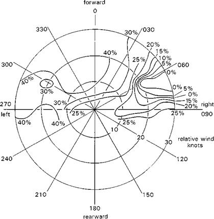
Figure 2.7 illustrates the tail rotor control requirements for early Marks (Mks 1-5) of Lynx at high all-up-weight, in the low-speed regime corresponding to winds from
|
Fig. 2.7 Lynx Mk 5 tail rotor control limits in hover with winds from different directions |
|
|
different ‘forward’ azimuths (for pedal positions <40%). The asymmetry is striking, and the ‘hole’ in the envelope with winds from ‘green 060-075’ (green winds from starboard in directions between 60° and 75° from aircraft nose) is clearly shown. This has been attributed to main rotor wake/tail rotor interactions, which lead to a loss of tail rotor effectiveness when the main rotor wake becomes entrained in the tail rotor. The loss of control and high power requirements threatening at this particular edge of the envelope provide for very little margin between the OFE and SFE.
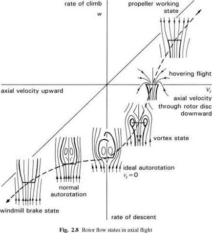
A second example is the so-called vortex-ring condition, which occurs in nearvertical descent conditions at moderate rates of descent (0(500-800 ft/min)) on the main rotor and corresponding conditions in sideways motion on the tail rotor. Figure 2.8, derived from Drees (Ref. 2.7), illustrates the flow patterns through a rotor operating in vertical flight. At the two extremes of helicopter (propeller) and windmill states, the flow is relatively uniform. Before the ideal autorotation condition is reached, where the induced downwash is equal and opposite to the upflow, a state of irregular and strong vorticity develops, where the upflow/downwash becomes entrained together in a doughnut-shaped vortex. The downwash increases as the vortex grows in strength,
leading to large reductions in rotor blade incidences spanwise. Entering the vortex-ring state, the helicopter will increase its rate of descent very rapidly as the lift is lost; any further application of collective by the pilot will tend to reduce the rotor efficiency even further – rates of descent of more than 3000 ft/min can build up very rapidly. The consequences of entering a vortex ring when close to the ground are extremely hazardous.