Viscous Decambering Stall Mechanism
The Displacement Body model combined with Glauert’s thin airfoil theory [8], sections D.2 and D.3, provides an intuitive explanation for the loss of lift at stall. This theory gives the general lift result
cg(a) = 2 па + в£0 (3.17)
for any thin airfoil. The lift intercept ci0 depends only on the airfoil’s camberline shape, and is most sensitive to the deflection angle of the camberline over the rear portion of the airfoil. These results also apply to more general airfoils, except with finite thickness the slope dc^/da = 2п will be somewhat larger.
|
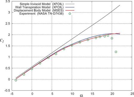
Figure 3.5: Comparison of eg (a) lift curves for GAW(1) airfoil at Re c = 6 million, Moc = 0.15, calculated by XFOIL [5] and MSES [6]. Experimental data is from McGhee et al [7]. |
In light of this result we examine the camberlines of the displacement bodies of the GAW(1) airfoil at the a = 0° and a = 16° operating points, shown in Figure 3.8. The large separation region over the upper rear of the airfoil at high а increases the displacement body offset An there, creating an upward deflection in its camberline which then causes the downward shift in the lift curve for that shape. This upward deflection of the effective camberline is called the viscous flap. The two resulting fixed-camberline eg (a) functions intersect the actual eg(a) curve for the airfoil, which in effect goes through a progression of ever-increasing upward viscous flap deflections which gradually reduce the lift from its strictly inviscid value. Maximum lift and subsequent stall occurs when this viscous flap decambering progression overpowers the inviscid lift coefficient gradient deg/da.


