Vortex Theory of Propellers
The Lanchester-Prandtl wing theory hypothesizes that each chordwise element of the wing can be treated as if it were a two-dimensional section acting in the local flow that results from the free-stream velocity in combination with the flow induced by the trailing vortex system of the wing. This same approach was extended to propellers by S. Goldstein in a classic paper [1] in 1929 when he obtained the solution to the ideal propeller by solving the potential flow problem of a helix immersed in a uniform stream. Unfortunately, Goldstein’s results are expressed in a semi-infinite series of
|
|
modified Bessel functions and are therefore not too easily handled for the general case.
An approximation to Goldstein’s solution was earlier obtained by Prandtl [2] which agrees closely with Goldstein the greater the number of blades or the smaller the pitch of the helical vortex sheet trailing from the propeller.
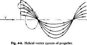
Consider the propeller shown in Fig. 4-6. From the Kutta-Joukowski theorem each element of the propeller blade must have a circulation of Г around it given by
dL = pe x Г dr. (4-26)
At the tips of the blades the section lifts must vanish. It therefore follows from Helmholtz’s theorem of vortex continuity that a vortex sheet must arise from each blade trailing downstream in a helical shape with a strength equal to the radialwise gradient of the bound circulation.
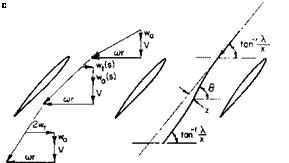
With reference once again to Fig. 4-5, the trailing vortex sheet induces the velocity w in the plane of the propeller. This velocity can be broken into two components, an axial component wa and a tangential component wt. Now consider the closed-line integral of the velocity taken around the dashed path shown in Fig. 4-6. Around the blades the integral will have a value of (—ВГ), В being the number of blades.
Along the vortex sheet the contribution from one side will cancel that from the other. Around the circle aft of the propeller the integral will have a value of
Jq 2wT(r, ф)г #.
The factor of 2 appears because the plane of this integral could have been taken infinitely far downstream of the propeller where the vortex sheet extends to infinity in both directions, hence induces twice the value that it would at the plane of the propeller. This, in fact, demonstrates that the line integral of the tangential velocity must increase discontinuously from zero in front of the propeller to its full value immediately behind it. This same conclusion results from consideration of the torque applied to the fluid by the propeller with the resulting change in angular momentum.
Because the dashed path of Fig. 4-6 does not cut any vortex sheets, it follows that the line integral of the velocity must vanish. Thus
f*2, it
ВГ = 2nrwT(r, ф) сіф. (4-27)
In the limit as В approaches infinity the velocity does not vary with ф so that
lim ВГ = Гж = 4nr wT(r).
B~> oo
The ratio of ВГ to Гда is known as Goldstein’s kappa factor к and can be obtained from Goldstein’s propeller theory. As stated before, however, it is approximated closely by Prandtl’s tip loss factor F. This factor is not to be confused with the effective radius В; F is a factor that varies with radius and allows the calculation of a continuous thrust distribution along the rotor radius.
Thus
Ajrr
Г = — F wT(r). (4-28)
D
The development of F as found in Ref. 2 is given by
F = – cos"1 ехрГ-f – (4-29)
n 2sin<£TJ
where фт is the helix angle at the tip. The bound circulation can also be related to the section lift coefficient by
Г = icC, F,
By combining the above with (4-28) we have
This equation is an implicit relationship for wT since Ve and oq are dependent on wT.
For reasons discussed later the induced velocity at the plane of the propeller is assumed to be normal to the resultant velocity in that location. Hence from the geometry of Fig. 4-5 the axial velocity wa can be calculated as
![]()
![]()
![]() or, in terms of VT,
or, in terms of VT,
(4-31)
The angle ф + oq is given by
The resultant velocity Ve can be found from
Hence, knowing a and P as a function of x and given a, we should be able to solve the system of Eqs. (4-29) through (4-33) for wT/VT, wjVT, (a, + ф), and VJVT. The thrust and power can then be calculated from
![]()
![]() rR
rR
corV^cCi cos (ф + a,)[£ + tan (ф + oq)] dr, о
or, in dimensionless form,
Kr=J a(^rj C‘ cos № + – rtl – £ tan (Ф + *i)] dx’ (4-34)
KP = J xcr^~^j C, cos (ф + a,)[fi + tan (ф + a,)] dx. (4-35)
The slope of the section lift curve a0 and the ratio of drag to lift є are functions of the local Mach and Reynolds numbers. However, their dependence on the Reynolds number, as far as propellers are concerned, can
normally be neglected. On the other hand, compressibility effects can become severe near the tip of a blade if the local Mach number exceeds the critical Mach, number. The estimation of e and a0 for M > Mcrit is often a difficult task because of the lack of sufficient experimental data. In the absence of specific data the following expressions can be used to estimate Cd and a0:
|
Cd – S0 + (ijC, + S2Cf |
+ A Cd, |
(4-36e) |
|
AC, = K(M – Mcrit)4 |
(AC, = 0 if M < Mcrit), |
(4-36b) |
|
Mcrit = Mcrit0 – WjC,, |
(4-36c) |
|
|
ao — a0iJl + fl4^4 + <210M10), |
(4-36d) |
![]()
 = constants in airfoil drag polar,
= Mach number of section,
= critical Mach number,
= critical Mach number for C, = 0, = constant,
= constants,
= dCJda for M = 0.
For a NACA 0012 airfoil section typical values of these constants are
|
<50 = 0.0085, |
К = 200, |
|
II О |
°olac = 0.1 Cf deg, |
|
S2 = 0.008, |
a4 = 1.438, |
|
crit„ = 0.725, |
a10 = —4.29, |
|
mY = 0.425, |
C, = 1.4. ‘max |
The effect of blade stall must also be considered in calculating CT and CP. Although it is possible to perform refined calculations by using lift curves extending beyond the stall, it is not considered worthwhile because of the uncertainties involved in determining С1т_ж; С1тшж depends critically on Mach number because of the occurrence of local shock stall and also varies considerably with blade roughness and irregularities in manufacture. It is recommended therefore that the C, m>i be used only as a limiting value on any calculated section C(.
Approximate Solution for a,-. The preceding equations are tedious to solve for wt or a; because of the implicit relationship of и,. Fortunately af can be
solved for directly if the angle a, is assumed to be small. From the geometry of Fig. 4-5
w, = Vrol, sin (Ф + a,).
Equating the above to Eq. (4-30) by using Ve ^ VR, we obtain
a. = i[-B + Jb2 + 4C] (4-37)
where
and
c = gfloQg – 0)
8xF cos ф
Observe that for x = 1, F = 0, so that a, = /? — </> at the tip. Hence the C, at the tip vanishes. This also allows us to calculate the angle фт in the expression for F, Eq. (4-29):
Фт = Ф + «і(х = 1) = (4-38)
These equations for a blade with washout at the tips may not hold at low values of the thrust coefficient if [iT becomes negative. Hence in any numerical calculations it is recommended that фт not be allowed to become negative. If фт does become negative, we must use a small positive value for фт, say, approximately one degree.
Normality in the Ultimate Wake. The velocity diagram in the ultimate wake of a propeller is shown in Fig. 4-7. Reference 3 shows that the resultant velocity and the induced velocity in the ultimate wake must be normal. This is apparently in conflict with the previous assumption of normality at the plane of the propeller. However, it is not so. We must remember that the wake behind the propeller contracts. The radius of a streamline from the axis at the propeller is larger than the radius of that same streamline in the ultimate wake. Hence to conserve angular momentum the average “2w(” immediately behind the propeller must be less than “2w,” in the ultimate wake. To circumvent the difficulties inherent in dealing with the ultimate wake normality is assumed in the plane of the propeller. The justification for this assumption lies in the fact that in the limit, as the number of blades become infinite, results from the vortex theory reduce to those obtained from momentum theory if normality is assumed in the plane of the propeller.
To show this let F = 1 (as В -> oo) so that
ВГ = 4n rwt.
From normality in the plane of the propeller
W, = i[cor – Jicor)2 – 4wa(V + vvj] The differential thrust is written:
dT = pBV(o>r — wt) dr.
A combination of these relations results in
dT = p(2nr dr^V + wa)2wa, which is in agreement with momentum theory.
 |
Corrections for Thickness and Wide-Blade Effects. As developed so far, the vortex theory of propellers is comparable to the lifting line theory of finite wings. For the typical aircraft propeller or helicopter rotor the theory is adequate. However, for broad-bladed propellers of high solidity it may be necessary to apply corrections to account for the blockage of the flow as it
passes through the blades and for the finite chord of the blades. To understand how these corrections are made, consider Fig. 4-8. Immediately in front of the propeller the velocity is composed of the free-stream velocity V,
the axial induced velocity wa, and the rotational velocity (or. As the flow enters the cascade of airfoils, the axial component must increase to satisfy continuity as the cross-sectional area of the channel decreases. As the flow progresses through the propeller, the tangential component of induced velocity increases from zero at the leading edge to its full value of 2иу at the trailing edge. Because of this, the flow traces a curved path which effectively reduces the camber of the sections. This correction to the camber can be determined graphically, but for purposes of numerical calculation expressions are developed to account for the variation of ну and thickness effects. The problem is linearized by calculating the effects separately. First consider the иу variation. It is assumed that ну varies linearly through the propeller from zero at the leading edge to 2wy at the trailing edge. If в is the slope of the flow at any point a distance of у from the leading edge, then approximately
![]() V + и-
V + и-
cor — (y/c)2wT
 |
Thus the change in в from the leading edge to the trailing edge is
л z Л0
*7 "l" (4-39)
For a circular arc airfoil this corresponds to a reduction in the angle of attack of the zero lift line of
Ав
Да = т. (4-40)
The effect of thickness is determined by approximating the airfoil with an ellipse of the same thickness-chord ratio. Again, if у is the distance from the leading edge,
From continuity
 2nrV = V(y)^2nr – Btmax
The angle 9 is given approximately by
 -! V(y)
cor
9 given by Eq. (4-41) traces out the path shown in Fig. 4-8. The departure of this path from a straight line is given by
![]() -г – = 9 — tan dy
-г – = 9 — tan dy
or
 |
The effective change in the angle of attack of the section due to thickness is
By substituting (4-41) for 9 and performing the indicated integration we
obtain the results
![]() 4 А(Т I max
4 А(Т I max
15 (A2 + x2) c
In the calculation of the performance of a given propeller the section angles of attack are reduced in the amounts given by (4-40) and (4-42). To produce a desired Г-distribution the section angles of attack should be increased by the amount of (4-42) and the camber ratio by (4-39).
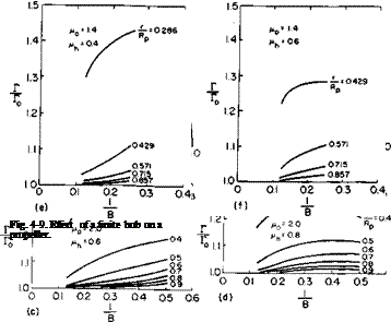
The Effect of a Finite Hub. Goldstein’s solution and Prandtl’s approximation to Goldstein’s solution assume that the action of the blades holds clear into the axis of rotation of the propeller. In other words, the propeller is assumed to have no hub. This is most often satisfactory, but in some applications in which the hub radius is appreciable with respect to the propeller radius a correction to the bound Г-distribution is required. The problem of the optimum propeller with a finite hub was first solved in Ref. 4. Here an infinitely long circular cylinder is concentric with the axis of the trailing helical vortex sheet and the strength of the vortex sheet is adjusted so that the velocities normal to the surface of the cylinder will
 |
vanish. This additional boundary condition modifies Goldstein’s results for a helix of given pitch so that the slope of the bound Г-distribution is zero at the hub. These results are presented in Fig. 4-9. These factors are the ratios of Г with a hub to Г without a hub. Hence to account for the effect of a
finite hub we multiply Goldstein’s kappa factors or Prandtl’s F-factors by the factors of Fig. 4-9 and then proceed with the same analysis used in the zero hub case.
Figures 4-9a and b show the effect of different hub sizes on the circulation
distributions of two – and eight-bladed propellers. The notation is the same as in the reference and is defined as
coR 1
rh = hub radius,
w = axial velocity of helical vortex surfaces = w0,
Notice that the departure from the zero hub case is much less for the eight-bladed propeller and is shown more clearly by Figs. 4-9c through /. Here, for constant values of r/Rp, the ratio of Г with a hub to Г without a hub is plotted versus the reciprocal of the number of blades.
Reference 3 presents the results of a comprehensive project on torpedo propellers but is, of course, applicable to any propeller. In this report it is shown that a finite Г can be maintained at the hub. For wake-operating, counterrotating propellers this is desirable. For single propellers in general, however, carrying a finite Г into the hub results in a hub vortex downstream of the propeller. The low pressure in the center of this vortex, acting on the rear face of the propeller hub or on any structure aft of the propeller, can detract seriously from the thrust of the blades. Hence for a single propeller with a large hub it is recommended that the bound circulation distributions be reduced to zero at the hub unless there is something like another propeller or a set of stator vanes downstream of the propeller to counteract the hub vortex.


