Airfoil Sections
The choice of airfoil sections for helicopter rotors requires special consideration because significant improvements in rotor performance can be realized with the optimal selection of airfoil shapes. This is of such fundamental importance to helicopter design that Chapter 7 is devoted to a basic understanding of the subject. Early helicopters used derivatives of NACA 0012 or NACA 230-series airfoils, which gave a reasonable compromise in overall performance. These can be considered as “first-generation” airfoil sections – see Fig. 6.17. Later, helicopters began to use a variety of airfoils sections that were optimized to match the aerodynamic requirements of each station along the blade. This is required
First generation airfoil sections
Second generation airfoil sections
‘High-speed" airfoil sections
Figure 6.17 Airfoil sections for helicopters have been specifically developed to meet the aerodynamic conditions actually encountered on the rotor.
because during each rotor revolution, the airfoil sections on helicopter rotors encounter a wide diversity of operating conditions. For example, for a representative blade station (say at 75% blade radius) the aerodynamic environment in which this section operates in hover and forward flight are different. On the advancing side of the rotor disk the blade sections may reach high subsonic speed and in high-speed forward flight they may penetrate into the transonic flow regime. This causes wave drag, and if the shock strengths become sufficiently severe, shock induced flow separation and stall may be produced.
On the retreating side of the disk, the blade tip sections operate at subsonic speeds, but at much higher angles of attack, eventually close to stall. Therefore, the blade sections must be thin enough to maximize the drag divergence Mach number, while simultaneously they must have some minimum thickness and incorporate some camber to give a relatively high C/max but still maintain low pitching moments throughout. No single airfoil profile will meet all these requirements and the airfoil(s) must be designed to reach a compromise between the requirements of all flight conditions, both at low and high airspeeds and also at high thrusts. Margins for maneuvering flight and turbulent air conditions must be factored in to the design to allow for sufficient performance. In general, the goal is to find airfoil sections that balance the advancing blade requirements (high drag divergence Mach number) with those of the retreating blade (high maximum lift at low Mach numbers), while maintaining a good overall lift-to-drag ratio throughout. This will help to maximize rotor efficiency throughout the flight envelope.
While rotor efficiency is often viewed simply as a hovering efficiency, forward flight efficiency (i. e., the effective lift-to-drag ratio of the rotor) is also important. But consider first the hovering efficiency. The airfoil requirements can be examined by rewriting the
figure of merit in another form to that shown previously. For a rotor with rectangular blades then
![]()
3/2
The mean lift coefficient of the rotor is Сц = 6(Cj/a) and it will be assumed that all the sections operate at the same Cd — Cd, an approximate but useful assumption. In terms of Ci and Cd the figure of merit becomes
Therefore, the figure of merit will be a maximum when all of the airfoils comprising the rotor blades operate at their best values of the ratio C^2/ Cd – see also Question 6.1. This result has been pointed out by many authors, including Gessow & Myers (1952), Prouty (1986), and Stepniewski & Keys (1984). While in practice not all the airfoils on the blade can operate at the same condition because of the varying Mach number and Reynolds number along the blade span, the forgoing result does show the need for good airfoil designs, in general, to obtain maximum hovering rotor efficiency.
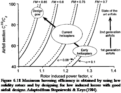
This requirement is summarized in Fig. 6.18, where Eq. 6.15 has been rearranged to solve for cV2 ICa as a function of the induced cower factor к for several values of rotor FM. It is
——- I, – M. – x
 |
clear that to achieve a state-of-the-art rotor design the induced losses should be low (by means of appropriate blade twist) and the value of cf^2/Cd for the airfoils should be large (through appropriate airfoil design and blade solidity selection). It would seem that values of FM of 0.80 or higher are only possible with an extremely careful rotor design (using optimal
|
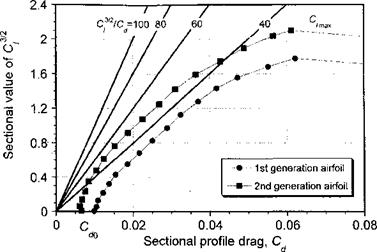
Figure 6.19 A form of 2-D drag polar for an airfoil showing that much higher values of 3/2 Cz /Cd are only possible through reductions in profile drag and increases in maximum lift coefficient. |
blade twist, planform and tip shape) and also by using very advanced airfoils, perhaps with flow control devices to delay the onset of stall (see page 401). It is apparent, however, that after the airfoils reach high maximum values of Съ/ /Cd (say over 80), further gains in rotor figure of merit through airfoil design improvements alone are very much harder to come by.
A form of drag polar for two representative helicopter rotor airfoils is shown in Fig. 6.19. One airfoil represents a first generation airfoil section with relatively modest performance and the other is a second generation airfoil with lower profile drag and a better value of maximum С/, that is, Qmax. Also shown are lines of constant cf/2/Cd from 40 (a modest but realistic airfoil performance) to 100 (an excellent but perhaps unrealistic performance). It is clear from Fig. 6.19 that improvements in cf/2/Cd come about by decreasing profile drag to as low a value as possible while simultaneously increasing the maximum attainable lift coefficient to as high a value as possible. It is for this reason that helicopter designers have strived for many decades to develop high-lift/low-drag airfoils that retain these characteristics over a wide range of operational Mach numbers – see Chapter 7. It is also apparent from Fig. 6.19 that the maximum values of C^2/Cd are obtained over a good range of operating lift coefficients, usually in the range 0.7 < С/ < 1.2, and so the rotor can operate at its maximum efficiency over a fairly wide range of disk loadings. This is a clearly beneficial result, so the rotor does not become as much of a “point” design. Delaying the onset of stall and the drag rise at higher lift coefficients obviously helps to further maintain rotor efficiency. However, it is not realistic to expect on a practical rotor that the best values of C^2/Cd can be achieved simultaneously at all blade sections, nor that 2-D airfoil measurements are entirely representative of the aerodynamic behavior of the airfoils on the rotor. Yet the results in Fig. 6.18 indicate the general design goals.
Clearly, one way to help minimize profile power and maximize figure of merit in hover is to consider the use of an extremely low drag airfoil. As shown in Section 7.8, the airfoil profile drag consists of two parts, namely pressure drag and viscous (or shear stress) drag. The pressure drag can be minimized by using relatively thin airfoil sections, although the use of thin airfoils has some disadvantages as well, mainly because of the possibilities of
achieving fairly low maximum lift coefficients. The viscous drag component, represented approximately by the coefficient C^0, can be minimized by carefully controlling the airfoil pressure distribution and maximizing the chordwise extent of laminar flow, at least for a range of low to moderate lift coefficients. This is called a natural laminar flow (NLF) section. Unfortunately, there are other aspects of airfoil performance, such as the need for low pitching moments and high maximum lift, that usually preclude the use of special low drag or NLF airfoil sections on rotor blades. Also, environmental factors tend to produce insect accretion and blade erosion at the blade leading edge, which can cause premature boundary layer transition and reduce the run of laminar flow in any case. In some circumstances surface roughness can adversely alter other aspects of the airfoil characteristics such as by lowering C/max and/or changing the stall characteristics.
A powerful parameter affecting the profile power of the rotor is the airfoil thickness. Using 2-D airfoil measurements given by Abbott & von Doenhoff (1949), the zero-lift sectional drag coefficient for the NACA symmetric series can be approximated by the equation
![]() (6.16)
(6.16)
where tjc is the thickness-to-chord ratio. The result is valid in the range 0.06 < t/с < 0.24. The effects of Mach number compound the behavior of the drag, but at moderate angles of attack below the drag divergence Mach number the effects of compressibility are small and are more sensitive to Reynolds number. Assume, for example, that a blade tapers in thickness from an airfoil with a 12% thickness-to-chord ratio at the root to an 8% ratio at the tip. Therefore, using Eq. 6.16 the drag coefficient can be written as
![]() Q0(r) = 0.007 + 0.025(0.12 – 0.04r) = 0.01 – 0.001г.
Q0(r) = 0.007 + 0.025(0.12 – 0.04r) = 0.01 – 0.001г.
The profile power coefficient can now be estimated using the blade element model where
![]()
![]() (6.18)
(6.18)
Evaluation of this expression gives a value of |<r(0.0092) compared to the value |cr(0.01) without the use of thickness variations (i. e., an 8% reduction in profile power). Typically, this would translate into an increase in figure of merit of between 1 and 2%. For a given rotor power or shaft torque, this would offer a 0.5-1.5% increase in overall vertical lifting capability (see also Question 6.8). This is significant; measurements by McVeigh & McHugh (1982) show a 5% gain in rotor figure of merit and a 25% gain in equivalent lift-to-drag ratio in forward flight through the use of advanced airfoil sections designed for lower profile drag and higher drag divergence Mach numbers.
The effects of Reynolds number variation of rotor profile power and figure of merit can also be estimated using this blade element approach. Based on the results shown in Section 7.3.2 it is apparent that the effects of Reynolds number on profile drag can be approximated from turbulent boundary layer theory by
![]()
 |
|
С*, =0.1166 Re-0 2,
which is based on an average of more than 40 different wind tunnel tests with the NACA 0012 airfoil, and this equation seems to offer a slightly better approximation in the higher Reynolds number regime (see Fig. 7.4). This suggests an increase in rotor profile power of about 15% when reducing the tip Reynolds number from 107 to 5 x 10⁵. Reducing further the Reynolds numbers to the values typical of micro air vehicles or MAVs (see Section 6.14 and Fig. 7.4) would suggest values of Cdo in the range of 0.03 with a corresponding fourfold increase in rotor profile power requirements. One approximation for low Re is to use the scaling
These high values of drag help explain the relatively poor hovering efficiency and low values of figure of merit of current rotating-wing MAVs (see Fig. 6.2 and Section 6.14) and the need for vast improvements in airfoil efficiency at low Reynolds numbers if these types of MAVs are to become more viable.
Consider now the effects of airfoil performance on the efficiency of the rotor in forward flight, which is explained by Stepniewski & Keys (1984). Consider the power requirements for the rotor in forward flight based on the results given previous in Chapter 5. For flight at some forward speed Voo (but high enough that Glauert’s approximation to the induced inflow is valid) and assuming the rotor thrust is equal to the weight of the helicopter, then the main rotor power required is the sum of its induced and profile losses, namely
P = ff^-+pA(QR?^( +4.65ц2), (6.22)
2pAVoo 8
where Co is assumed to represent the average profile drag coefficients of the airfoils on the blades. All of the other symbols have their usual meanings. We seek a result for the effective lift-to-drag ratio of the rotor, (L/D)r, in the forward flight condition in terms of airfoil properties. The rotor L/D ratio can be approximated by L/(P/ Voo) = W/(P/ Voo) – see Section 5.5.3. Therefore the ratio of D/L can be found using the standard form of the power equation to get
|
_6(CA_6( W V or / o – pA(QR)2J ‘ |
Proceeding further it is convenient to write the rotor thrust in terms of a mean operating lift coefficient Cl, which working on the assumption that all blade sections operate at the same Q (as shown in Section 3.4.6) is given approximately by
With this result (D/L)r for the rotor can be written as
Differentiating Eq. 6.25 with respect to Cl to find the value that will give the best (L/D)r gives

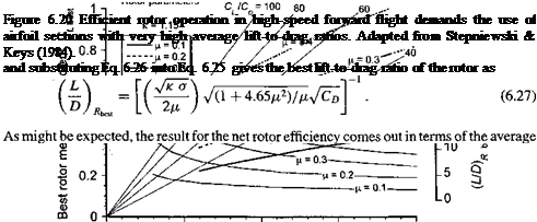
drag coefficients of the airfoils comprising the rotor.
The results are summarized by the composite set of curves in Fig. 6.20 in terms of the mean operational lift coefficient required to reach the best L/D ratio (for a rotor of given solidity) at a given advance ratio versus the mean drag coefficient, Co, of the airfoil sections. The corresponding results for the best L/D ratio of the rotor are also shown. It is assumed that the induced factor к is known a priori. To understand this plot consider a given airfoil family with a known average value of Cd . The results show that for efficient flight at higher speeds the rotor must be operated at a relatively larger mean lift coefficients, which clearly requires airfoils with very good lift-to-drag ratios. The need for very high-speed flight (i. e., /л > 0.4) demands airfoil sections with extremely good average characteristics, that is, with 2-D sectional lift-to-drag ratios approaching 80. It will be apparent that for a helicopter of given weight operating at a given /x the value of Cl can only be reduced by increasing rotor solidity (Eq. 6.26), although this must always be at the expense of blade weight and some loss of hovering efficiency. These results, however, illustrate rather nicely some aspects of the design Irade-offs when develoning я trulv high-sneeH rntnr Rvstem. where it is clear that only so much performance can be gained from airfoil section developments and increases in rotor solidity. To further improve cruise efficiency at high speeds requires that the high average Cl/Cd of the blades be maintained by simultaneously delaying both the onset of advancing blade compressibility effects and retreating blade stall.


