Blunt-Body Flow
6.4.1 Bow-Shock Stand-Off Distance at a Blunt Body
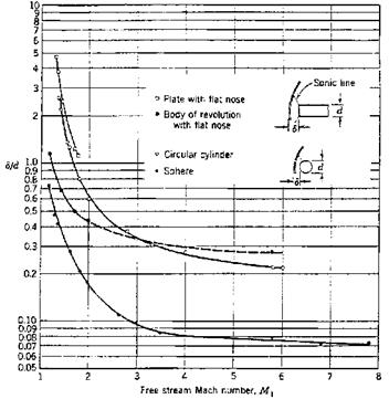
We have noted in the preceding sub-section that the shape of the bow-shock surface is governed by the free-stream properties and the effective body shape. These also govern the stand-off distance A0 of the bow-shock surface from the body surface. In particular the shape of the body nose has a strong influence on Ao, Fig. 6.18, [4], where 5/d = A0/2Rb.
The smallest stand-off distance is observed for the sphere, the largest for the two-dimensional cases. In general Ao is smaller at axisymmetric bodies, because there the stagnation-point flow is relieved three-dimensionally, in contrast to two-dimensional flow. With increasing free-stream Mach number all curves approach asymptotically limiting values of the bow-shock stand-off distance A0 (Mach number independence).
For the bow-shock stand-off distance at spheres and circular cylinders, approximate analytical relations are available for sufficiently large Mach numbers, say, Ыж ^ 5, see, e. g., [22].
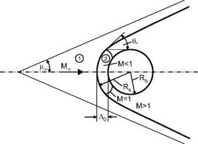
We consider a sphere with radius Rb, Fig. 6.19. It is assumed that the bow-shock surface in the vicinity of the flow axis lies close and parallel to the body surface, and thus is a sphere with the radius Rs.
Further assumed is constant density in the thin layer between the body surface and the bow-shock surface. With these assumptions the shock standoff distance A0 at a sphere with radius Rb is found [22]:
Here є is the inverse of the density rise across the normal shock portion, Fig. 6.19
![]() Pco _ PI _ (7 – l)Mf + 2 Ps P‘2 (7+1 )Mf
Pco _ PI _ (7 – l)Mf + 2 Ps P‘2 (7+1 )Mf
![]()
|
|
|
Eq. (6.120) can be expanded in a power series to yield
![]()
![]() ^0 = Rs — Rb = є R
^0 = Rs — Rb = є R
A similar relation for the circular cylinder reads [22]
For sufficiently large free-stream Mach numbers є can be approximated for both normal and oblique shock waves, eqs. (6.70) and (6.84), by the value for Mi ^ ж
 |
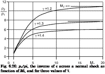
where we must demand 7 > 1. For our purposes this is a fair approximation for Mi ^ 6 at least for 7 = 1.4, as can be seen from Fig. 6.20, where the inverse of є is shown as function of Mi, and for three values of 7.
In a flow with large total enthalpy the temperature behind the bow-shock surface in the vicinity of the stagnation point region rises strongly. Accordingly the ratio of specific heats 7 decreases. If we take an effective mean ratio of the specific heats 7 as a measure for the bow-shock stand-off distance at large free-stream Mach numbers, we obtain for instance for the sphere, eq. (6.122), to first order
This result tells us that the bow-shock stand-off distance A0 at a body in hypersonic flight is largest for perfect gas, and with increasing high – temperature real-gas effects becomes smaller as the effective mean y is reduced. A rigorous treatment of this phenomenon can be found in, e. g., [23, 24].
We illustrate this phenomenon with data computed by means of a coupled Euler/second-order boundary-layer method for a hyperbola of different dimensions at hypersonic Mach numbers, Table 6.3. (See also the example discussed in Sub-Section 5.5.1.)
|
Table 6.3. Flow parameters of computation cases of a hyperbola with laminar boundary layer at hypersonic Mach numbers.
|
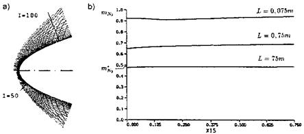
The bow-shock stand-off distance in the case 1 (perfect gas computation), is more than two times larger than that in the case 2 (equilibrium gas computation), Fig. 6.21 a), Table 6.4.
In reality, however, the situation can be more complex, depending on the size of the body, and hence on the first Damkohler number of the problem, Section 5.4. This is studied by means of true non-equilibrium computations for three different body sizes, cases 3 to 5 in Table 6.3. For the small body with L = 0.075 m (case 3) only a small degree of dissociation is found, Fig. 6.21 b). The reason is that due to the small absolute bow-shock stand-off distance and the large flow speed not enough time is available for dissociation to occur, DAM 1 ^ 0.
For the large body with L = 75 m, case 5, the situation is different. The absolute bow-shock stand-off distance is large, and the degree of dissociation, too, Fig. 6.21 b). At the stagnation point, X1A = 0, it compares well with the degree of dissociation m*N2 (= ^N2) found behind an isolated normal shock wave with the same flow conditions, hence we have an equilibrium situation, DAM 1 ^ to.
That mN2 at the stagnation point is a little smaller than m*N2, is due to the fact that between the bow-shock surface and the body surface a further compression happens, and hence a rise of the temperature from 5,600 K
|
Table 6.4. Thermodynamic models of computation cases for a hyperbola at hypersonic Mach numbers (see Table 6.3), and results. The ratio of boundary-layer to shock-layer thickness S/Л is that at half the body length (X1A = 0.375 in Fig. 6.21).
|
|
Fig. 6.21. Results of coupled Euler/second-order boundary-layer computations of hypersonic flow past hyperbolas. a) bow-shock shapes [25], upper part: perfect gas (case 1), lower part: equilibrium real gas (case 2). b) mass fraction mN2 (= шn2) at the hyperbola’s surface for different body dimensions, cases 3 to 5 [26]. X1A is the respective location on the body axes, m’N2 the degree of dissociation behind an isolated normal shock wave. |
behind the (isolated) normal shock to approximately 5,900 K at the stagnation point, which increases the degree of dissociation.
Case 4, L = 0.75 m, finally lies between the two other cases, and is a typical non-equilibrium case, DAM 1 = O(l), Table 6.4. Regarding the almost constant mass fractions for the cases 3 to 5 in Fig. 6.21 b), we note that an adiabatic wall was assumed throughout. Therefore the levels of surface temperature remain approximately the same along the hyperbola contours, and with them the respective mass fractions.
The results prove that with a coupled Euler/second-order boundary-layer computation formulated for non-equilibrium flow also the limiting cases of “frozen flow” and “equilibrium flow” can be handled. For purely inviscid flow computations of this kind, problems have been observed in the vicinity of the stagnation point of blunt bodies, where in any case the flow locally approaches equilibrium, which makes a special post-processing necessary [27].
The differences in the bow-shock stand-off distances between case 1 and case 3, as well as between case 2 and case 5, are due to the fact that we have viscous-flow cases. The approximate ratio of boundary-layer to shock-layer thickness S/A at 0.5 body length L is given for each case in Table 6.4. These ratios are approximately the same for cases 1 and 2, and also for the cases 3 and 4, because the Reynolds numbers are the same, respectively comparable for each pair. Of course the surface temperature levels are much higher in the cases 3 and 4, because of the much larger free-stream Mach number, and hence the boundary layers are thicker, Sub-Section 7.1. Case 5 finally, with a very large Reynolds number, has a very small boundary-layer thickness compared to the shock-layer thickness.
The results given in Table 6.4 point to the potential problem of a wrong determination of the shock stand-off distance compared to free flight. This can happen in a cold hypersonic tunnel, in a high-enthalpy facility, or with a computation method, because of the strong sensitivity of the shock standoff distance on the high-temperature thermo-chemical behavior of the flow. Such a wrong determination can lead, for instance, to an erroneous localization of intersections of the bow-shock surface with the aft part of the flight vehicle—we discuss examples in Sub-Section 9.2.1—but also to errors in drag prediction etc., related to the interaction of the bow-shock surface with embedded shock waves and expansion phenomena.[66]
The absolute value of a potential error in the shock stand-off distance, of course, depends on the effective radius of the stagnation-point area, e. g., the blunt shape of a re-entry vehicle at large angle of attack. If we take as example a body at high Mach number with an effective nose radius of Rb =
1.5 m, we would get in flight, with an assumed mean 7 = 1.2 in the shock layer, a shock stand-off distance of approximately 0.1 m. For perfect gas with Y =1.4 this distance would be approximately 0.2 m, which is wrong by a factor of two.
On the basis of the above relations we obtain an overview of parameters in the shock layer in the nose region of a body, i. e., near the stagnation point, which are affected, if high-temperature real-gas effects are not properly taken into account there. The pressure coefficients cp2 and cp2t in that region for large free-stream Mach numbers M1 become independent of the Mach number, eqs. (6.72) and (6.73), see also Section 6.8, and also do not vary strongly with Y. Hence we can assume that for given large Mach numbers the pressure also does not vary strongly, and that the mean density in the layer between the bow shock and the body surface in the nose region will be proportional to the inverse of the mean temperature there:
pnieansh0ck layer ^ rpl ■ (6.126)
‘meanshock layer
With that result we get qualitatively the differences of flow parameters in the shock layer at the nose region between the flight situation and the perfect-gas situation, i. e., with an inadequate simulation of high-temperature real-gas effects, Table 6.5. The actual differences, of course, depend on the nose shape, and speed and altitude of flight compared to the parameters and the flow situation in ground-simulation. Whether they are of relevance in vehicle design, depends on the respective design margins [2]. However, our goal is to have uncertainties small in ground-simulation data in order to keep design margins small [28].
|
Table 6.5. Flow parameters in the nose-region shock layer of a blunt body at large free-stream Mach number M1. Qualitative changes near the stagnation point from the flight situation with high-temperature real-gas effects (baseline) to the perfect-gas situation.
|


